Magnetostriction, a Source of Noise in Transformers

Given the spiraling energy consumption and the ever-increasing demand for power and distribution transformers, more and more of these units are being installed near residential areas. As a result, there is a growing demand for low noise transformers, and there are strict regulations for noise control that transformer manufacturers have to comply with. However, there are a number of challenges that a designer faces when it comes to reducing noise due to magnetostriction.
Transformer’s Active Parts
Transformers consist of two main active parts: the core and the windings. The core of a transformer consists of a stack of laminations made of high permeability grain-oriented electrical steel sheets. The laminations are very thin but can be quite large in the other two dimensions. For example, Fig. 1 shows the laminations in the core of a 3-phase transformer as they are being assembled.

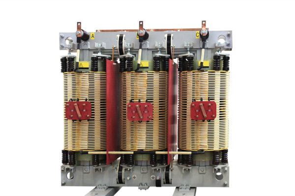
The windings, shown in Fig. 2, are made of copper, or aluminum conductors wound around the core, providing electrical input and output. The currents in the windings generate the magnetic field that runs through the core.
Source of Noise
There are many sources of noise in a transformer. One of the sources is the vibration resulting from changing dimensions of the laminations in the core due to changing magnetic field through magnetostriction.
It is important to mention that magnetic forces, including magnetostrictive forces, have harmonic components with a fundamental frequency twice the power frequency. The fundamental frequency would be around either 100Hz or 120Hz. Consequently, any of the harmonics in the frequency range of up to 20 kHz can constitute an audible noise.
Several factors play a role in mitigating noise. Of those, the lamination material and the construction of the core make a significant difference. Therefore, it is crucial to understand the magnetostrictive effect on the core based on the material property and the assembly at induction levels under actual operating conditions.
What Exactly is Magnetostriction?
As a brief background introduction, magnetostriction is a property of magnetic materials that causes them to change their physical dimensions under the influence of a magnetic field. When the magnetizing field changes periodically, the core dimensions change periodically. This periodic change causes vibration and, therefore, noise.
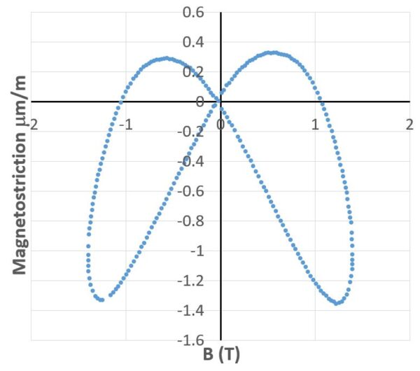
However, one thing to note about magnetostriction is that the change in the physical dimensions is minute making the measurement of this effect very difficult. The graph in Fig. 3 shows an example of results obtained from measurement. Here, the magnetostrictive strain is measured for several cycles and is represented as a function of the magnetic field. The butterfly-shaped graph represents the strain as a change in the flux density over one cycle. As shown, the physical dimensions changes are in the range of one micrometer per meter.
Magnetostriction Forces in a Grain-Oriented Laminated Core
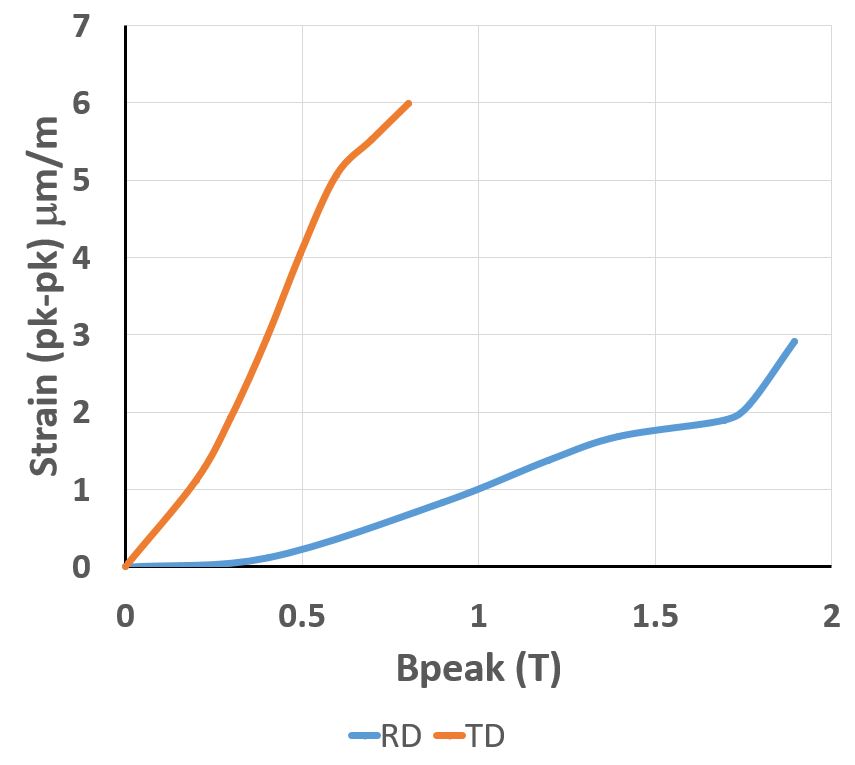
Another complication is that the transformer industry uses grain-oriented electrical steel. This means that the material’s magnetic properties are anisotropic. It also means that the magnetostriction properties are highly anisotropic. Measurements, in this case, would be even more difficult. In general, material property measurements for grain-oriented steel are available in two directions. The significant anisotropy, shown in the graph in Fig. 4, displays the peak-to-peak changes in the strain as a function of flux density. As shown, the strain along the transverse direction (orange) is much higher when compared to the one in the rolling direction (blue).
Above all, what the designer needs is the evaluation of the noise from the magnetostrictive effect. For such an evaluation, the vibro-acoustic analysis software first requires the magnetostriction forces from an electromagnetic simulation.
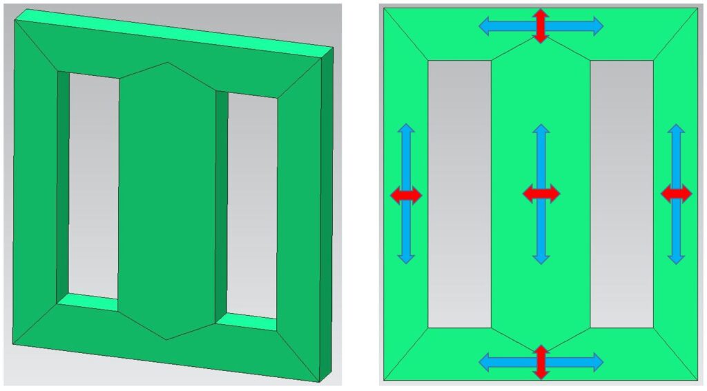
For example, the core shown in Fig. 5 is a stack of grain-oriented electrical steel laminations aligning the flux path along the rolling directions of the different segments.
To perform the simulation, the system requires the magnetic material properties in the rolling and transverse directions, and the structural properties as input.
The soon to be released Simcenter MAGNET 2021.1 includes a numerical model that takes the uni-axial measured data and converts it to an anisotropic property data. In other words, the system automatically reconstructs the entire 3×3 strain tensor. The tensor would be for any direction of the magnetic field from just one curve per material direction.
Significant Magnetostriction Forces at Joints and Interfaces
The plots shown here have been generated with the soon to be released Simcenter MAGNET 2021.1. The solution offered in Simcenter MAGNET 2021.1 addresses the simulation challenges by providing a capability for the user to enter the magnetostriction material property data, as well as the structural properties.
The figure below represents the magnitude and the direction of the magnetostriction force density. What is significant is that by visual inspection, it is possible to see which sections of the laminations are contracting and which sections are expanding, and as a result, cause vibration.
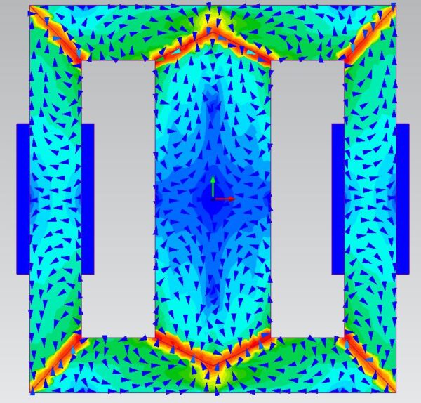
As shown in Fig. 6, the magnetostriction force density around the joints is the strongest. This effect is in agreement with strain-gauge measurements. Fig. 7 shows the magnetostriction force density arrow plot at one of the corners (L-joint). Here the designer can examine the rotating force field more clearly.
In fact, the joint region is quite complex because of the different overlaps possible between the laminations. There are usually large deformations taking place in these regions.
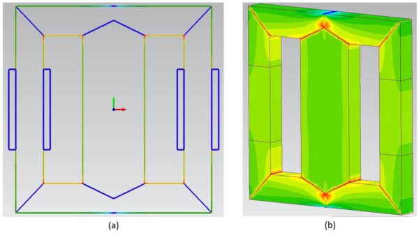
Magnetostriction forces are mainly internal forces in the core. However, there is another component of magnetostriction force. This is the force acting on the interface between two different materials. This force represents the discontinuity that exists at the interface. The field plots in Fig. 8 show this component of the force density on the interface between the core and the surrounding air. Certainly, one cannot ignore this significant component of the magnetostriction force.
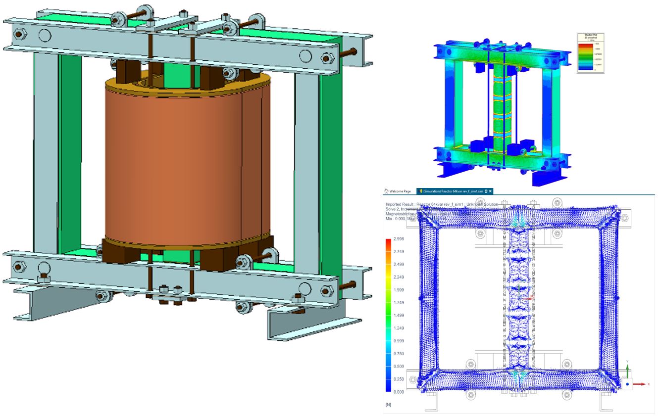
Further Vibration and Noise Analysis
Finally, the designer is interested in the resulting vibration and noise. This requires the nodal magnetostriction forces as loads in structural analysis software. The nodal magnetostriction force is the sum of the internal force and the force on the interface. For example, the force field plot of the reactor shown in Fig. 9 is the nodal forces exported to Simcenter 3D for vibration and noise studies.