Machine Frame Digital Simulation: Crafting an Efficient FEA Workflow (Part 2)

Editor’s Note: This article is the third in a series of articles by David Haag of Haag Enterprises, an advanced digital engineering shop specialized in delivering product development and industrial equipment and automation services.
In Part 1 of this series, I shared my approach to crafting an efficient workflow using Simcenter Femap, which was basically a high-level overview of the finite element modeling process. In this post, we’ll dive into some more specific topics that will help us organize models as they grow in complexity.
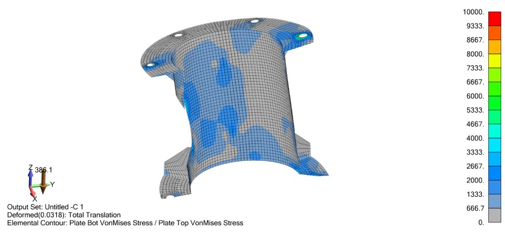
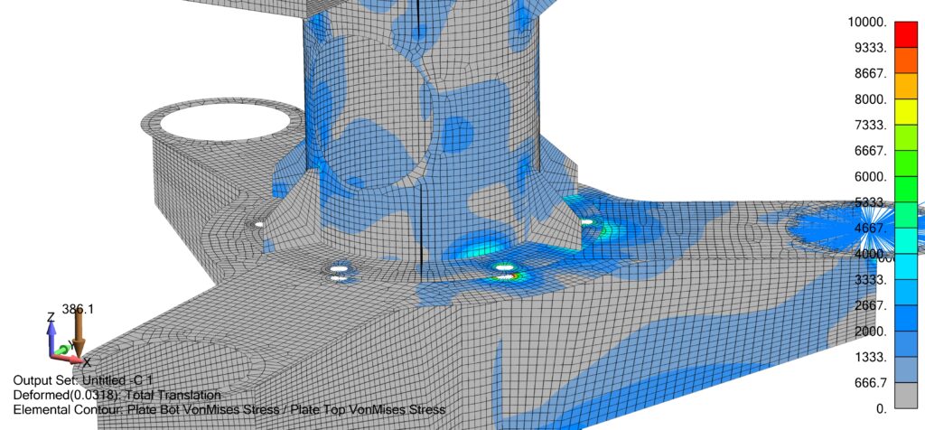
The solver has finished and it’s time to review your results, but with larger models, it becomes a challenge due to the number of entities on the screen. For instance, Figure 1 below is a display of the entire model; when trying to review the bolted connections and/or contact stresses occurring between the weldments, we simply can’t do it due to flange plates blocking our view.
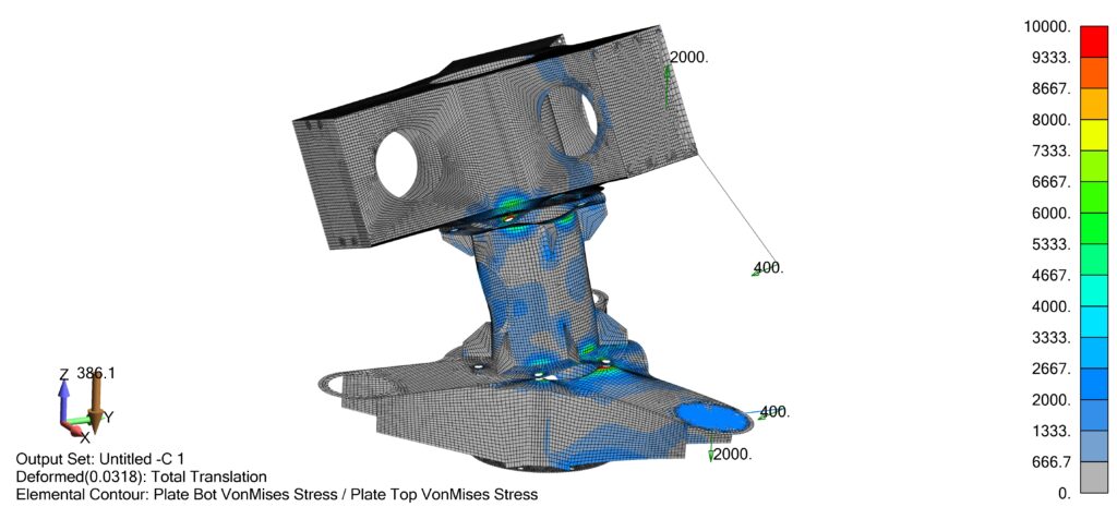
In the following sections, we’ll briefly introduce a few powerful tools to help you navigate during model build along with interpreting results. Please also note that these tools are typically used in combination as can be seen in the demonstration video at the end of this post.
Groups
You may be familiar with Layers; however, it has some limitations so I want to introduce you to Groups.
The Groups command allows you to organize the model by geometry or FEM entities that can be recalled later. Think of it as visual display states that you can save for later. You can view these groups individually, in a boolean fashion, or all at once. Also note that an entity can be used within multiple groups, unlike layers.
Group creation can be done automatically choosing a type (e.g. material, property, solid, surface, element, etc.). Once a group has been created, we can add to it manually or turn on the “Automatic Add” option and anything created from that point forward will be part of that group.
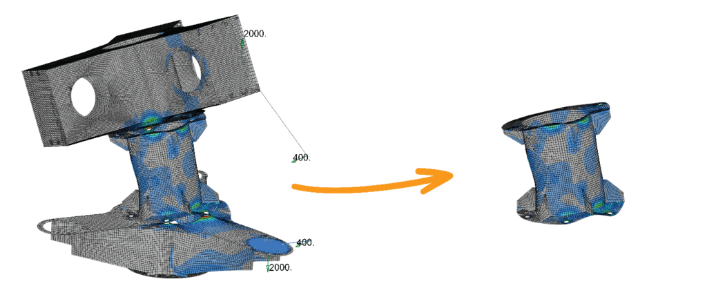
Figure 2 shows a Middle Weldment group that was created by generate using Solid. We can activate this group by double-clicking it, then we can Display Only by right-clicking on the group and selecting Show Active Group.
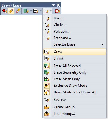
Draw / Erase Toolbar
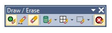
This toolbar offers a different method of selecting entities in order to temporarily show or hide them. Entities are selected using any combination of commands by selecting geometry, mesh, and/or areas. The draw mode will show the entities added to the list and the erase mode simply toggles then to a hidden state.
We could have isolated the middle weldment only using this tool, but once cleared, we would have lost that display state; however, we do have the option to create a group from the current display state.
Slicing/Sectioning using Clipping Plane
Clipping planes are straight forward, as you choose or create a plane on the fly, which will be used to slice through the model and the side being displayed can be toggled. For CAD users, this is a standard way of interrogating parts and assemblies, but it lacks the advanced functionality of Groups and Draw Erase commands.
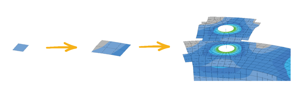
Grow/Shrink Elements
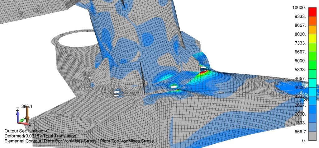
This is an option within the Draw/Erase toolbar and allows us to choose a single element or region of elements and increase the display of neighboring elements by choosing Grow and alternatively, decrease the display by choosing to shrink. A likely subsequent action could be saving the display as a Group, which could quickly be restored later. For instance, if this is an area of interest, we may save it to a group, re-run the analysis using different parameters or using a different solution set, with the ability to display the same entities to use as comparison.
Scaling the Deformed Model
In post-processing, we have the option to display the model as undeformed and deformed. Additionally, with the undeformed state, we have the option to view actual deformations or scale these deformations by some percentage. The advantage is being able to see how the material behaves, which helps with identifying the next step, which could be mesh refinement, adjusting plate thickness, adding stiffeners, etc.

Summary
The Group and Draw/Erase commands within Simcenter Femap help us quickly organize our models as they grow in complexity, leaving us more time to create accurate digital models. They can be used as standalone or in combination, as you’ll see in my video below.
I hope this provided value and inspires you to practice/implement into your daily workflow. If you have specific questions, leave a comment below or send an email to info@haagenterprises.com.
Thanks for your time!


