Lessons from the trenches: Thermal Management Systems for Electric Vehicles

Designing the Next-Generation Thermal Management Systems for Electric Vehicles
CSEG is a Design, Modelling and Simulation consulting firm that I co-founded in 2011. We specialize in thermal management systems and vehicle powertrain energy consumption modeling.
From our 10 years of experience, I’ve found that one thing is quite clear. There is a very distinct difference between the best-in-class vehicle manufacturers and the rest of the industry. The biggest difference we see from a Gen 1 to a Gen II vehicle is the big reduction in the thermal energy consumption, and system design complexity.
In our modeling and optimization work, the prime directive was to understand where and when the energy consumption was happening. Our team developed high-fidelity mathematical models of the system/Powertrain. They then allowed the math models to tell us how to reduce the energy consumption and costs from the system. However, just creating a good and relevant math model is harder than it looks. It is not the mathematics that is hard, but knowing what physical phenomena to include, which to leave out and to what level of fidelity to include in the phenomena that is modeled.
Given that this field is being actively re-engineered on by almost every car company, I’m sharing a few important lessons and observations when designing the next generation Thermal Management system.
Lesson #1 … Energy consumption will make or break your EV range promise
Thermal Management is the largest energy consumer on the battery outside of driving energy.
Anybody can cool the battery or heat the cabin. But can you do it energy-efficiently with the simplest possible system? This was what separates the winners from the losers. There is almost a 250% difference in the thermal management energy consumption and cost between the top and the bottom quartile carmakers.
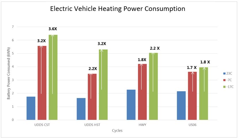
Thermal system energy consumption is the highest in winter. This is primarily due to the temperature difference between the outside and inside the cabin. On a cold winter day (say -5°C), the temperature difference between the cabin (which is at 25°C) and the outside (-5°C) is 30°C. Whereas, on a hot day (38C), the temperature difference between the outside and the cabin (22°C) is 16°C. The thermal management system therefore must work harder at maintaining this larger temperature difference in the winter which leads to the winter energy. Many drivers already intuitively know that this results in a shorter driving range in the winter.
Most newly established EV companies do not fully appreciate the magnitude of energy consumption difference a well-engineered thermal management system could make. Their first generation of the vehicle is focused on getting the vehicle to work properly, making it look appealing and creating a successful launch. A year after launch, consumer feedback starts to come in on the poor winter EV driving range and then the OEM must figure out why. Then figure out how they can make the real-world range closer to the promised range.
Lesson #2 … Uncover where the opportunities lie by competitively benchmarking your thermal management energy consumption with best-in-class
How does your vehicle’s energy consumption compare with other best-in-class vehicles, preferably those that are in their second or third generation?
You should measure and compare not just driving, heating and cooling energy but also the control strategies. Control strategies in many of the best-in-class vehicles contribute to the over 30% difference in performance and energy consumption of the thermal system. The control strategy will also clue you in on additional strategies and physical phenomena that the benchmark vehicle is leveraging.
As an example, in the Tesla Model Y, when the battery needs warming, the control algorithm looks at the temperatures of different components in addition to the cabin to see if there is excess heat available to glean. If the cabin is warm, the blower turns on to transfer the heat from the cabin to the cooling system and the battery.
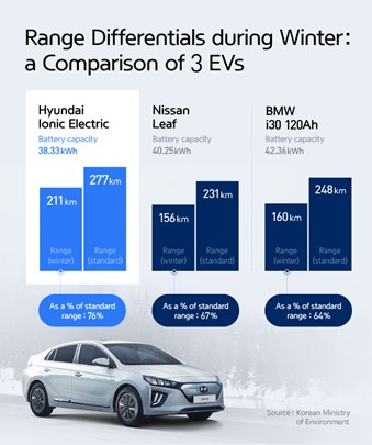
Also, see alongside, this range impact study published by Hyundai. Their relentless focus on thermal management system design and optimization has led to a much better winter range than their rivals.
Some additional vehicles readily available for energy benchmarking can be found at www.powertrainlive.com
Lesson #3 … Develop and track a nuanced energy consumption metrics/scorecard at several real-world operating conditions
One might ask, “Why should I worry about intermediate steps and metrics? If I design for the worst-case scenario, say at -40°C ambient, using a 10kW electric (PTC) heater, wouldn’t that be sufficient?” Once you have designed for the worst-case scenario, then you are good for all the intermediate cases, right? Yes, BUT.
By designing for a worst-case scenario, you will not be using energy for other operating conditions in an optimal/economical way. In the real world, the car might only see the -40°C ambient temperature handful of days and a lot milder (say 0°C or -5°C ambient) majority of the time.
A simple metric of “Energy required to heat the cabin” is a good start to bring focus on energy consumption by accessories but is insufficient. You will need a nuanced metric that looks at the energy consumption at multiple operating conditions. For example:
“What is the energy required to heat the cabin at 10°C ambient Temp? 0°C ambient? -10°C, -25°C and -40°C? Ditto for cooling, what is the energy required to cool the cabin on a 35°C and 45°C day?”
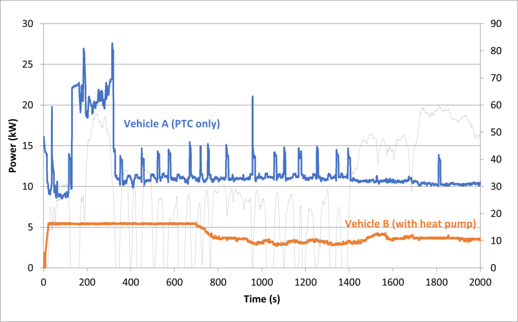
Paying attention to energy consumption in real-world winter conditions will lead to implementing technologies that are best for the driver and the range in the real world. At milder winter temperatures, there are much more efficient solutions such as heat pump systems. When used cleverly, one could combine these technologies (such as a smaller PTC heater and a heat pump) to meet the performance requirement, whilst using less power. See below an example between an established EV that uses a PTC heater only vs one that blends in both PTC heater and heat pumps.
Lesson # 4 … Calculate the energy required for each mode of operation from first principles.
Some people call this the pen-n-paper method. Before you jump into designing the system you need to bookend your problem with simple calculations and assumptions. For example, “What is the energy required to cool or heat the cabin/battery/electronics using basic thermodynamics equation?”
Let’s look at an example of cabin cooling from 60°C to 20°C in say 5 min. Calculating the energy required for this cabin cooling will involve calculating the volume of air, thermal mass and physical properties of contents in the cabin and understanding the exact energy you will need to drop the temperature of the air and materials from 60°C to 25°C.
This type of exercise is very valuable and will help in a couple of major ways:
Firstly, it will allow you to question many assumptions that go into the problem. For e.g., you will notice that the cabin was at 60°C for an ambient temperature of 40°C. So, you can question why the cabin is so much hotter than the ambient and perhaps if there was something you can do about it. The answer is Yes. And a few astute carmakers use passive technologies such as solar glazed glass or purging cabin air with the outside to keep the temperature lower when the car is soaking in the sun.
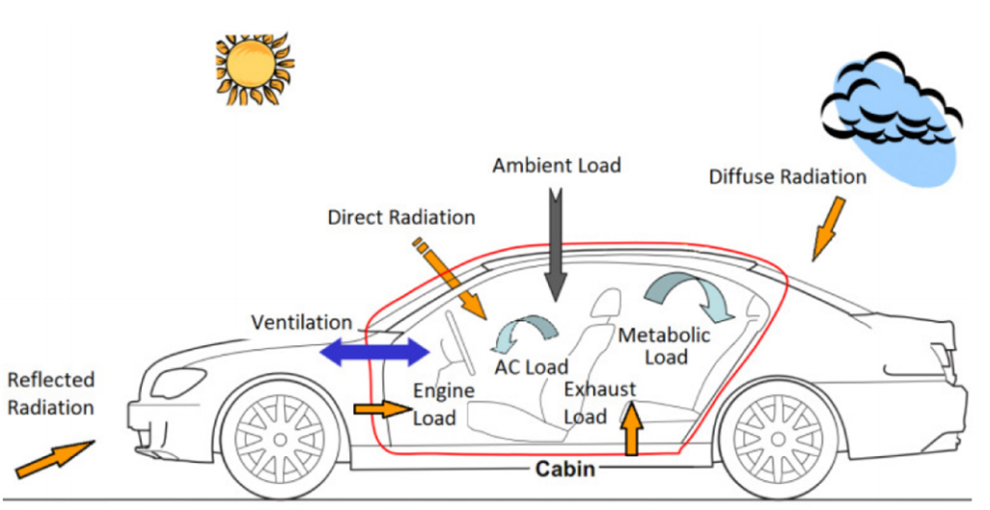
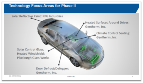
Thinking another way, you might ask yourself, “Am I really trying to cool the insides of the car and the air for cabin comfort? Or am I trying to keep the driver cool?”. In that case, human physiology comes into focus and becomes an important factor to consider. Where exactly to cool the driver to provide the best comfort is an active area of work in advanced thermal management. One might want to look up Gentherm’s Climate Seats to get a better understanding of where personalized cooling and heating is headed.
Here is another example of related technologies being assessed by National Renewable Energy Lab which shows the benefits of passive technologies.
Secondly, calculating the energy required from the first principles will allow you to get an absolute bottom number for the energy required. For example, if you calculated that you need to remove 5kW of heat from the cabin, you will then know the right size cooling/Air conditioning system to design.
If then you notice that to remove 5KW from the cabin the chiller needs to be 10kW, you will know that there is a 5kW wastage of energy somewhere along the line from the chiller to the cabin. This hopefully will trigger a new line of inquiry towards a lean and efficient system design.
Lesson #5 … A complete system simulation model is key but lead with the questions first.
Every simulation model MUST be geared towards answering a specific question. We regularly get requests from major carmakers with an objective such as to model the heat pump system to answer many design questions.
The truth is that there is no one full cooling system simulation model that can answer all questions. Every model has assumptions, missing components and physical phenomena (on purpose) in order to make the simulation model practical and timely. In order to figure out which physical phenomena to model, which to leave out, one must know the exact objective of the simulation model.
Asking specific questions such as, “I need to determine the right chiller size that will work in this system.” will help you determine the assumptions and complexity that you will need in the simulation model.
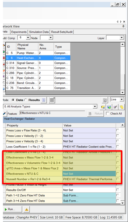
Let me provide a very specific example from a heat exchanger component model from Simcenter Flomaster.
When modeling a heat exchanger, you have many options to specify the thermal performance of the heat exchanger –a simple constant heat load (say 5kW), a constant effectiveness (say 75%) or a detailed thermal performance map that a supplier typically provides (say kw vs kg/s vs kg/s) among many others
How would you know which option is right for this specific instance? If the focus of the system model is on other components, and your solution is not sensitive to having a constant heat load from this heat exchanger, then you should specify a constant heat load and save yourself a few days of data gathering.
On the other hand, if what the model is solving for is sensitive to the heat exchanger heat load, and it must be determined from the fluid flows, then a thermal performance map from the supplier will be needed in the model.
Lesson #6 … Anticipate and leverage secondary effects on thermal system
The design choices you will make in the thermal system design will trickle through many other performance characteristics of vehicles. And vice versa. Let me illustrate with a couple of examples.
The ADAS technology, while in place for safety, adds thermal loads to the thermal management system. Self-driving technology (computers, sensors, etc) can consume anywhere from 2.5kW(for experimental set-ups) to 250W for optimized systems such as the Tesla self-driving set-up. 2.5kW is nearly 50% of driving energy and will impact not only the range but also the thermal load on the battery. Here is a post I wrote a few years ago on this.
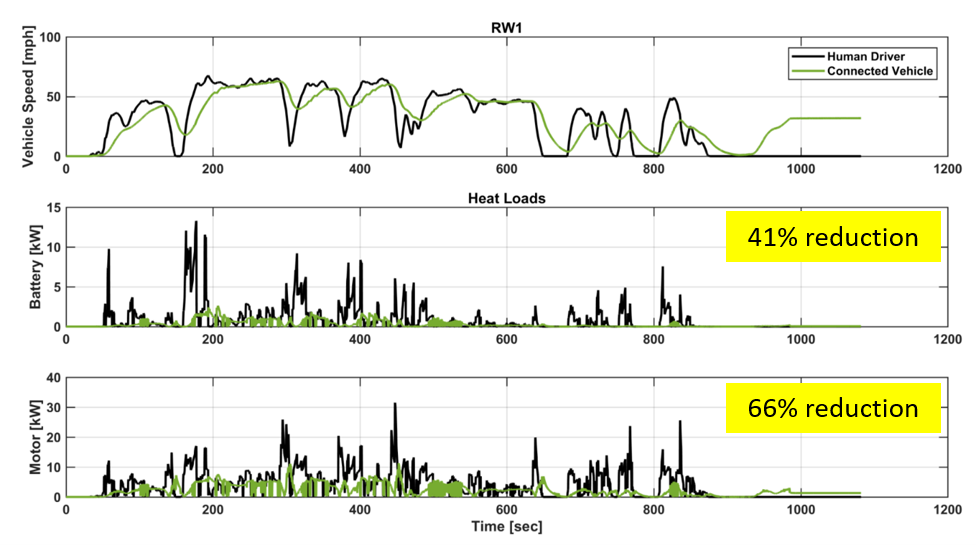
On the other hand, autonomous driving behavior can be tuned to drive in an eco-friendly way. Which can decrease energy consumption, increase the battery range and reduce peak thermal loads by up to 80%. CSEG’s recent study (illustrated in the graph) shows the impact of eco-friendly autonomous driving on battery and motor heat loads.
In addition to safety and comfort, the ADAS features have the opportunity for battery range extension and peak thermal load reduction, which will impact component sizing in the thermal system.
Here is a chart from the study that shows ADAS driving (shown in green line) impacts the transient thermal load on the battery and the motor.
In Summary:
An optimized and well-designed thermal management system is the primary enabler in delivering the published battery range in the real world. Developing the next-generation thermal management system for your vehicle will require a focused system engineering and benchmarking of the thermal management system. Therefore, the key steps we use and propose are:
- Uncover where the opportunities lie by competitively benchmarking your thermal management energy consumption with best-in-class vehicles
- Optimize control strategy. Control strategy can contribute system up to 30% improvement without any added component cost.
- Develop a nuanced scorecard to track the thermal management system performance at several real-world operating conditions
- Calculate energy required for each mode of operation from first principles
- A complete system simulation model is key but lead with the questions first.
- Anticipate and leverage secondary effects
Author

Sudhi Uppuluri is the Chief Technology Officer and co-founder at CSEG, an automotive software and consulting firm with a focus on powertrain design and modeling, vehicle thermal management, energy consumption, controls development, thermal system architecture development and energy-efficient fleet routing.
Sudhi is also the Chief Technology Officer of GreenRoute technologies, which extends EV range and cuts carbon emissions through energy-efficient routing.
He teaches a course on Thermal Management at the University of Wisconsin Madison. He is the chair of the SAE technical committee on thermal management. He holds a master’s in aerospace engineering from the University of Illinois at Urbana-Champaign and a Certificate in Strategy and Innovation from the MIT Sloan School of business.


