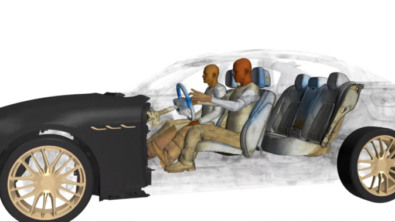
Achieving lighter vehicles with the use of composites

Achieving lighter vehicles by virtually mastering the resin transfer molding process of composite parts
Which factor has the largest impact on the energy efficiency of a vehicle? This question is important if we want to produce cars that consume less and, therefore, that contribute less to air pollution and global warming. If you ask this question to a group of engineering students, their first replies may be related to the technology of the engine or to smart driving techniques. The answer, though, is simpler than that: the factor that influences most the energy efficiency of a vehicle is its weight.
You can think about the relationship between weight and energy efficiency in this way: the useful work a car does is related to transporting you and your body mass a certain distance; however, each time your car is taking you somewhere, it is not only doing the work of moving your weight and that of the other passengers, but also the work of moving the weight of the vehicle. The weight of a car can be around 1,500kg for a mid-sized car. By any measure, this involves a huge waste of energy!
There are good reasons for cars to be heavy, mostly related to passenger safety and comfort. Therefore, a question that current research is trying to address is how to manufacture lighter and less energy-consuming cars that still have the properties needed to make them durable and safe for their occupants. Advanced materials, such as composites, may be part of the answer, since they can offer a combination of mechanical properties and weight reduction that helps to achieve this goal. However, for composite materials to routinely replace heavier materials in the production of vehicles, production processes that meet the needs of the automotive industry are essential. Computer-Aided Engineering (CAE) tools can play a key role in enabling this by allowing to simulate and optimize the manufacturing processes and to predict the quality of the resulting pieces under given process conditions.
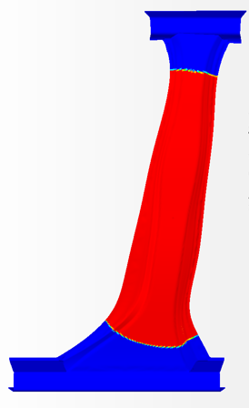
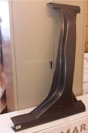
B-pillar (left) and simulation model of the B-pillar, showing the infusion flow front (right).
As part of its effort to develop CAE tools for composite manufacturing, Siemens Industry Software has partnered with Sirris and Com&Sens to investigate and validate the simulation of the manufacturing of a car’s B-pillar with Resin Transfer Molding (RTM). RTM is one of the key manufacturing technologies of composite structures. Different stages present in the RTM manufacturing include draping, i.e. ‘wrapping’ a textile reinforcement onto a mold; infusion, where a resin impregnates the dry reinforcement, and curing/demolding, where the resin solidifies (you can read about curing simulations in this other blog entry). Ideally, the infusion stage during RTM should be designed to minimize dry-spots and voids in the final piece, while simultaneously minimizing the time to infuse the dry reinforcement. Modeling and simulation technologies can be instrumental in this optimization.
In this study, the B-pillar of a passenger car was manufactured via RTM at Sirris. Prior to the infusion, optical fiber sensors enriched with Fiber-Bragg gratings (FBG) were integrated inside the mold. This allowed to locally track the flow front progress during the infusion manufacturing process by following the changes in the sensor signals, thus providing valuable experimental reference data.
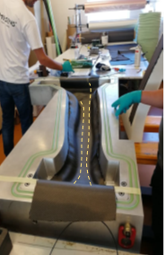
Optical-fiber sensors were carefully introduced in the B-pillar mold in order to track the resin flow during the RTM process.
The RTM process was simulated using Siemens PLM software. The draping of the dry woven textile on the mold was computed using Siemens Fibersim. This software applies a kinematic approach to determine the fiber orientations after draping. Then, the resin flow through the B-pillar dry reinforcement as installed in the mold was simulated using Simcenter Star-CCM+. The flow simulation used the fiber orientation data extracted from Fibersim to consider realistic fiber orientations and an analytical model to incorporate the effect of the shearing of the fabric on the permeability tensor. The flow front was tracked using the Volume of Fluid approach.
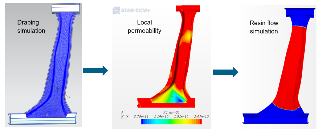
The steps in the simulation sequence are: draping simulation; mapping of fiber orientations and computation of local permeability tensor in the flow model, and resin flow simulation.
The time at which the resin flow front passes the virtual location of the sensor was used to compare the simulation results with the experimental measurements. The comparison is shown in the figure below:
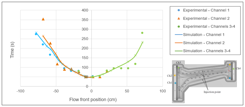
Time at which the flow front passes through each sensor location (symbols are experimental data; continuous lines are simulation results); on the right bottom corner, a scheme showing the sensor locations is shown.
The RTM simulation capabilities demonstrated in this study could be used for other types of industries beyond the automotive industry and complete Siemens current solution for composite materials. Further investigations are ongoing with Sirris in the framework of this topic to investigate how to address additional manufacturing challenges using Siemens simulation tools.


