Bringing together 3D CAD and system simulation, the key to an efficient digital thread
Utilizing 3D CAD models to model systems and systems-of-systems can significantly improve the efficiency and effectiveness of the product development process. By closely linking system simulations to the physical design, engineers can make informed decisions, optimize designs, and address potential issues early in the development cycle. This integration is a crucial component of the digital thread in modern product development.
In Simcenter Amesim, CAD Import provides powerful tools to generate system models from 3D CAD geometries. Once 3D CAD models are imported, the tool can be used to assign system components to 3D bodies and then retrieve automatically parameters of interest like lengths, diameters, area, volumes, and more. In the end, the tool is able to convert a 3D CAD model into an equivalent system model in Simcenter Amesim using different physics domains.
Connect CAD data and system simulation
By leveraging the capabilities of your 3D CAD and system simulation software, you can ensure that any changes made in the 3D CAD model are automatically and accurately reflected in the simulation model. This helps minimize the risk of errors and discrepancies during the product development process.
And here comes the challenging part when you need to capture a new design revision; how do you apply the changes of the 3D CAD data needed for system simulation directly on an existing system model and boost your productivity. Because your analysis is relevant only if they are based on the latest design.
For 3D CAE simulation, even if the CAD data needed for simulation is different to that used for design, the connections can be tracked and managed by a PLM system. This way, each item in the 3D CAE analysis bill of materials (BOM) is related to a corresponding item in the original CAD BOM.
With System Simulation, finding a direct relationship with the original BOM is a big challenge and something more difficult. In addition, you can enhance your system model by adding sensors, actuators or completing with other systems physics. Figuring out which components need to be updated in your simulation is only possible if you know where you started.
Simulation-driven design
Delta robots are commonly used in factories for picking and packaging, as they have the ability to perform up to 300 picks per minute. More recently, Delta robots have been adapted for use in 3D printing.
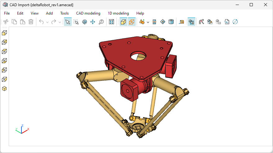
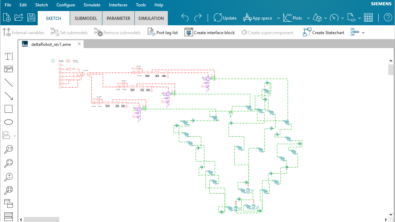
Below is a model of the robots that can be created in Simcenter Amesim.

The mechanical part of the model (the green components) was generated using 3D CAD mechanism data. The electric system was then added, which includes sensors, electric motors, and control logic. This enables the end effector to follow a predefined path.
To stay on top of the latest changes as the design evolves, you need to know which relevant components of your complete system model to update without interfering with the components you want to keep. Ultimately, you want your model to be ready for analysis without spending hours reconnecting all the components.
Comparing CAD-based models
Simcenter Amesim’s CAD Import Model Upgrade tool allows us to compare the existing system model with the updated one generated from new CAD data in a side-by-side view. The tool highlights the differences between the two models, such as new revisions to existing components or components that need to be added or removed from the model.
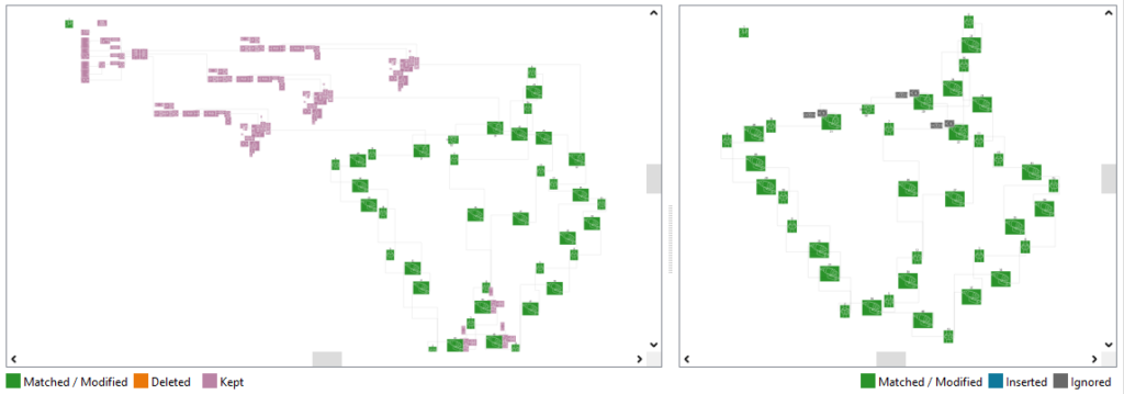
In the comparison of two model structures, certain components are highlighted in green to identify their matches in both views. The parameters of these matched components may have different values, which are updated in the final system model.
On the other hand, the components highlighted in purple are retained as they are in the final model structure. This information is displayed only on the current model view for upgrading purposes.
The comparison results are actionable and the user can make choices to perform all necessary updates. Upon completion, the system will alert the user.
Not really a revisions comparison tool
The Model Upgrade tool is different from revision comparison tools as it identifies matches between corresponding sections of model structures instead of generating reports on files that originate from the same source. This is why identical sections are highlighted.
To illustrate the tool’s functionality, let’s take the example of a simple hydraulic piping system where some parts have undergone significant modifications.
To go further
The tool primarily depends on the system description that is created from the 3D CAD data. Therefore, it is not limited to 3D data only. As long as you can extract the required data to describe your system, you can create a model in Simcenter Amesim or modify an existing one.
Using a product lifecycle management (PLM) solution and a solution in place simulation process and data management (SPDM), you can empower System Simulation at any stage of the design cycle, from a 2D diagramming to a 3D CAD.
Have a look at how to elevate MBSE workflows in the digital thread with Simcenter and Teamcenter solutions here.
Learn more on the latest Simcenter Systems 2310 release
Read the what’s new blog post or watch the video below: