Thermal management in 3D IC: Challenges, modeling and design strategies

You are likely here because thermal issues have become the primary constraint shaping your 3D IC design decisions. As 3D integration pushes more performance into smaller footprints, thermal behavior is no longer a secondary consideration. Thermal management in 3D IC increasingly determines whether a design can meet performance, reliability and time-to-market targets, or whether thermal limits quietly dictate architecture choices later in the flow.
If you are working with stacked dies, advanced packaging or heterogeneous integration, the pattern is familiar. Power densities increase rapidly. Heat has fewer and longer paths to escape. Assumptions that are held for 2D designs begin to break down, often late in the design cycle when changes carry significant cost and risk. What appears acceptable at the die level can quickly manifest as a system-level thermal constraint.
This article focuses on how thermal management in 3D IC actually works in practice, why heat behaves differently in vertical stacks and how engineers can analyze and manage thermal risk earlier and more predictably. The intent is to provide clarity you can apply during design, not abstract theory.
Thermal management in 3D IC explained in one minute
Thermal management in 3D IC is the discipline of characterizing, predicting and constraining temperature behavior across vertically stacked dies so performance, reliability, yield and lifetime targets can be achieved. Unlike 2D SoC designs, heat in a 3D IC must traverse multiple active layers, interfaces and materials, which increases thermal resistance and heightens sensitivity to localized power density.

Figure 1.Illustration of thermal hotspots in a 3D IC
In practical terms, 3D integration concentrates power while limiting natural heat spreading. Without deliberate thermal planning, temperature rise can outpace available cooling capacity, constraining operating frequency and accelerating aging mechanisms.
Effective thermal management in 3D ICs therefore begins early and evolves continuously, spanning architectural definition, stack organization, package design and system integration.
Why 3D ICs create extreme thermal challenges
3D IC architectures fundamentally alter heat transport. When active dies are stacked, heat generated in upper layers must conduct through lower dies before reaching a heat sink. Each interface introduces additional thermal resistance, increasing temperature gradients and sensitivity to placement decisions.
Power density further compounds this effect. Stacking logic, memory or heterogeneous functions places more switching activity into a smaller volume. Even when total power is comparable to a 2D implementation, localized heat flux often increases significantly.
Thermal coupling between dies adds another layer of complexity. Activity in one layer can elevate temperatures in adjacent layers, even when their individual power profiles appear modest. These interactions are examined in more detail in the Siemens podcast and article The hidden heat challenge of 3D ICs and what designers need to know.
Taken together, these effects make thermal behavior a system-level constraint rather than a single-die issue.
Understanding heat flow paths in 3D IC designs
Heat in a 3D IC follows paths defined by thermal conductivity, interface resistances, and boundary conditions, not just the shortest physical distance. It propagates through silicon, bonding layers, interconnects and package structures, with each element influencing overall heat removal efficiency.
Through-silicon vias (TSVs) and bonding interfaces serve a dual role. Electrically, they enable connectivity. Thermally, they can either facilitate vertical heat conduction or introduce localized bottlenecks, depending on material properties, density and spatial distribution.
Packaging introduces additional boundaries. Heat must transition from the die stack into substrates or heat spreaders, where interface resistances and material mismatches can dominate the total thermal path. Accurate thermal management in 3D IC therefore requires visibility across die, package and system levels. Optimizing any single layer in isolation often shifts thermal constraints rather than alleviating them.
Thermal modeling techniques for accurate 3D IC analysis
Effective thermal management in 3D IC depends on modeling heat early and refining that analysis continuously as design fidelity increases, rather than treating thermal behavior as something to be checked only at the end of the flow. Early-stage thermal models support package and stack exploration, enabling architects to evaluate architectural trade-offs before placement, routing and physical constraints become fixed.
At this stage, abstraction is intentional. Simplified models allow teams to characterize relative temperature behavior across different stack configurations, power distributions and interface assumptions. As the design matures, these models are progressively refined with detailed geometry, material properties and boundary conditions, preserving continuity from early-stage package exploration through design signoff.
Steady-state analysis is typically used to characterize worst-case operating temperatures, while transient analysis captures how temperature changes under dynamic workloads over time. In stacked designs, transient effects frequently expose thermal constraints that steady-state analysis alone does not reveal, particularly when activity migrates dynamically across dies.
From a system perspective, traceability is critical. Thermal assumptions established early must remain linked to power intent, placement decisions and package structure as model fidelity increases. Integrated chip-package thermal co-design flows support this continuity, enabling true IC to system thermal modeling instead of disconnected point analyses.
When thermal analysis is embedded directly within the design flow, rather than positioned as a downstream verification task, teams can evaluate trade-offs proactively and reduce late-stage iteration.
Proven thermal management strategies for 3D IC designs
There is no single cooling technique that universally addresses thermal challenges in 3D IC because thermal behavior depends on stack topology, power density, packaging, cooling strategy, and workload profile. Successful strategies combine architectural choices, material optimization and system-level evaluation within an integrated chip-package thermal co-design flow.
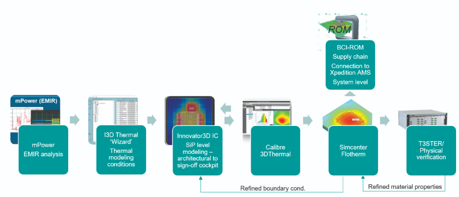
Figure 2. Siemens’ integrated thermal analysis flow for 3D ICs
Stack organization is one of the most influential levers available. Under many common configurations, placing higher-power dies closer to the heat sink can reduce peak temperatures by shortening vertical heat conduction paths. Because this decision directly influences temperature distribution across the stack, it is most effective when evaluated early, while architectural flexibility remains.
Thermal interface materials (TIMs) also play a disproportionate role in overall thermal behavior. Bonding layers and thermal interface materials frequently dominate total thermal resistance, meaning incremental improvements at interfaces can yield meaningful temperature reductions across the entire stack. These effects are often underestimated when interface assumptions are fixed too late in the design process.
Thermal strategy is closely tied to the chosen integration approach. Different architectures introduce different thermal constraints, and these must be evaluated in context rather than assumed. Teams that assess thermal behavior alongside electrical performance, mechanical stress and packaging constraints gain a clearer view of the full constraint space.
From a practical standpoint, embedding thermal analysis directly into the design flow reduces reliance on manual interpretation and late-stage fixes. By integrating thermal evaluation from early-stage package exploration through design signoff, teams improve predictability and reduce costly iteration across the 3D IC design flow.
Key takeaways for managing thermal risk in 3D IC
- Thermal management in 3D IC is a system-level discipline, not a late-stage verification task. Temperature behavior emerges from the combined interaction of architecture, power intent, placement, materials, packaging, and reliability considerations.
- Early architectural decisions shape thermal outcomes. Stack order, die placement, interface assumptions, and package boundaries often determine temperature limits long before detailed physical design begins.
- Keeping thermal analysis connected across the design flow improves predictability. When early thermal assumptions remain traceable as model fidelity increases, teams gain clearer insight into performance margins, reliability risk, and operating limits.
- Bringing thermal analysis forward reduces late-stage rework. Evaluating thermal trade-offs early enables informed design decisions while flexibility remains, minimizing costly iteration and downstream mitigation.
- With sufficient visibility and discipline, thermal constraints become a design input rather than a limiting surprise, enabling more confident and robust 3D IC architectures.
Thermal management in 3D IC FAQs
Why is thermal management more difficult in 3D IC than 2D ICs?
Thermal management in 3D IC is more challenging because heat must conduct through multiple active layers and interfaces before reaching a heat sink. Each layer adds thermal resistance, increasing sensitivity to power density and hotspot formation.
When should thermal analysis start in a 3D IC project?
Thermal analysis should begin during architectural planning. Early models help guide decisions such as stack order, die placement and power distribution, which are difficult or costly to change later.
How do TSVs affect thermal behavior in 3D ICs?
Through-silicon vias can either aid or impede heat flow. Their thermal impact depends on material composition, density and placement relative to heat sources.
Are advanced cooling techniques always required for 3D IC designs?
Not necessarily. Many thermal constraints can be managed through architectural trade-offs and interface optimization. Advanced cooling is typically introduced when system-level constraints cannot otherwise be met.
What is the most common mistake teams make with 3D IC thermal management?
A common mistake is treating thermal analysis as a late-stage verification activity. By that point, design flexibility is limited and mitigation options are more costly.
How does system-level thermal modeling improve reliability?
System-level thermal modeling reveals interactions between power, placement and packaging over time, helping teams manage thermal stress and design for long-term reliability.