Process Improvement: Reduce your programming time by analyzing your workflows
The following is a summary of a presentation that I delivered at this year’s PLM Connection conference titled, “Process Improvement: Reduce your programming time by analyzing your workflows.” The presentation addresses the challenges of having a rapidly growing number of parts that need to be machined. If this sounds like you, then you’ll want to read this article.
Process Improvement: Reduce your programming time by analyzing your workflows
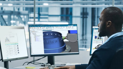
There is an increasing need for our NX CAM customers to machine a growing number of parts. Do you often ask yourself, “How can we be more efficient?” To do this you will need to reduce system programming time and cost, and reduce NX CAM calculation time. With these changes you will be much faster with NX CAM and will ultimately help to reduce manufacturing costs.
How do customers typically approach this challenge of becoming more efficient?
In most scenarios you will use application program interface (API) to automate workflows, implement featured-based machining (FBM) to automatically create NC Programs, create templates to reduce programming time, update to latest release to utilize new functionality, or update to latest release for improved performance. In many cases these “typical approaches” won’t help significantly.
What can you do differently? Analyze the existing NC-Programming Process
First, identify the pain point areas and potential bottle necks, based on parts, work-flows, use-cases. To optimize and reduce the NC programming time look at several areas . Analyze possible pain point areas to identify what consumes the most time. These areas include fixture design, documentation, tools (Creation/Selection/Feeds and Speeds, etc.), programming, NC Code Simulation, NC Code Output, and NC Setup. Which areas are bottlenecks and have potential for optimization?
Step 1: Analyze your whole NC Programming process! Measure time of each task on a variety of typical parts. In this example analysis, 42% of time is spent on NX CAM programming – preparing the manufacturing process, 30% of the time is spend on creating the set up (fixtures), and 13% on documentation.

Step 2: Conduct a detailed look at each of the big time contributors for further analysis. In the example, we would look at NX CAM Programming first. Collect information on time spent on individual NX CAM programming steps. Use a stop watch to measure time for each task. In this example, defining the operation is taking up most of the time, followed by verifying operation and defining UDEs.

Step 3: Analyze operation steps. What are the operations that consume the most time? Look for automation potential. Time can be reduced significantly if operations can be automated, ideally FBM but also API. In this example, Point to Point (PTP) and Planar Milling use the most time.

Use alternative Operations & Workflows
With Point to Point at 42%, what is the optimization potential? You should use FBM / manual hole-making because contrary to PTP it has more efficient methods to collect geometry. Manual hole-making is feature-based which offers many benefits. You can reduce time by using feature recognition instead of repeated manual selection of holes. You’ll also have better visualization of the in-process work piece (IPW) at all stages of programming. And, last, you can reduce time further by using full automation.
In this example, Planar Milling uses 25% of time. Where is the optimization potential here?
Use Floor Wall Milling / FBM. Why? Using Floor/Wall operations is much more efficient since boundary selection takes much longer compared to selecting floors & walls. No need to define part & blank boundaries. Better visualization of IPW at all stages of programming, in particular if parts are machined from multiple sides. Shown here, the next major area of time use is, Create Setup. Here you want to time and analyze exactly where you time is being spent. Is it, preparing parts, tool selection, adjusting fixtures or fixture design?

Use Manufacturing Resource Library (MRL)
The manufacturing planning requires the management of different components to build the CAM setup. On the one hand the part that needs to be machined starting with the blank part. The machine needs to be set-up using the fixtures to clamp the part. For the tool path generation the required list of cutting tools are needed. All these resource need to be managed in a colaborative environment. For this we provide the Manufacturing Resource Library.
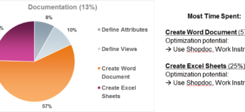
And, finally in the example, documentation used 13% of the time. Here 57% of the time is spent creating MS Word docs. The Optimization potential here is to use Shopdoc, Work Instructions. Another big time taker is creating MS Excel spreadsheets. Here too the optimization idea is to use Shopdoc, Work Instructions. Use Shopdoc to automatically create shop floor documentation.

Use Work Instructions (NX 10.0.2)
Work Instructions give you the ability to define a specific documentation sheet to any object in the program order view of the CAM operation navigator. A user can create Work Instructions through non-machining operations – Measuring, Cleaning, Coating, and Program header & footer. These operations will allow documentation attachments, interact with post, generate operation time, but do not produce tool path. These instructions are usually not embedded within the NC programming itself but are kept in parallel as loose documents which are not synchronized with the NC tasks. This makes life very difficult if changes occur.
You can find more information about NX CAM 10 on our web pages or on the Siemens NX for Manufacturing community.