Making the Jump to Five-Axis Machining Easier
First appeared in MoldMaking Technology magazine, Gardner Publications, Inc., USA. www.moldmakingtechnology.com

Improvements in CAM software help bring the benefits of five-axis machining to mold and die manufacturing.
Most mold and die shops rely on three-axis machines to do the bulk of their milling work. Five-axis machines were not considered sturdy enough to mill hard materials used in Class 1 mold cavities. Moreover, five-axis programming was harder to learn and program. In general, these statements remain true.
These challenges limited the use of five-axis machining to the more complex parts, such as those often found in aerospace applications that cannot be machined with only three axes. However, significant improvements in CAM software systems—with new programming techniques making the transition from three-axis to five-axis programming easier than ever before—have enabled many mold and die shops to switch to five-axis machines.
Recent field tests indicate that with a 10 percent increase in programming effort, five-axis machines can improve machining productivity up to 30 percent. Parts with deep cavities and small, vertical corners are the primary targets. On a three-axis machine these features require long tools with smaller diameters. Milling tools are classic cantilevers—held on one end with force applied at the other end. Any tool length-to-diameter ratio of more than seven requires considerable attention to cutting forces or problems due to tool deflection will result.
In fact, a 20 percent increase in tool length increases the deflection at the tool tip by 50 percent. Five-axis machines solve this problem by accessing these tight areas by tilting the tool away from the adjacent walls which then allows the use of shorter, stubbier tools. Mold and die hard milling with deep cavities and fine features next to tall walls benefit the most. This is especially useful with high-speed machines at higher spindle speeds where the resonance vibration can wreak havoc when combined with tool deflection problems.
3+2 Axis Machining
Due to the programming complexity of five-axis machining, some shops use a simpler, more versatile alternative: 3+2 axis machining. Here a machining area is divided into sub areas and each one is machined with a different, fixed tool axis (see Figure 1). The tool axis is changed when the tool is not cutting, and then remains fixed while the tool is engaged with the material in a given area. 3+2 axis machining has been a standard with newer CAM software in which surface machining operations support localizing the machining area with a trim boundary and allows an independent tool axis different from the Z axis of the machining coordinate system.

Figure 1: The divide-and-conquer approach – split the machining area into separate regions and create a different toolpath with unique fixed tool axis for each.
With holder collision checking, these 3+2 surface machining operations machine as much as the short tool and specified tool axis will allow. The areas that could not be reached are marked with a system created boundary. This allows users to localize machining to these uncut areas with the same tool, but a different tool axis.
While 3+2 axis machining provides better kinematic stability during cutting, it does have some disadvantages. The divide-and-conquer programming strategy requires extensive trim boundary creation. Also, transition areas between different tool axis regions leave tool marks on the surface, which requires hand polishing.
Traditional Five-Axis Machining
Simultaneous five-axis programming requires a significantly higher level of programming expertise. This approach is commonly used for many aerospace and medical components where fewer, well-sculpted surfaces are machined in a single toolpath operation. Mold and die components do not fall into this category where thousands of surfaces are machined at once. There is no easy way to drive the toolpath along the parametric lines of these surfaces. In most cases, it is very unlikely the mathematical definitions of these surfaces form matching parametric lines. Also, simultaneous five-axis machining requires well sculpted drive surfaces that are hard to find in mold/die components. Some new CAM software offers a processor that uses a streamline technique, so it is more forgiving of the modeling smoothness and continuity of the surfaces being machined. This type of processor allows tool axis definition based on drive surfaces defined by flow curves that are independent of the surfaces being machined. This results in a smoother, more accurate toolpath and tool axis.
Five-Axis Programming for Three-Axis Programmers
New software advances assist programmers in applying multi-axis programming techniques directly to traditional fixed-axis operations. For example, some software offers a five-axis waterline machining processor. The programming input required for this toolpath is similar to that of three-axis programming. The resulting toolpath also resembles a three-axis waterline toolpath, except for the variable tool axis (see Figure 2). The tool axis is automatically tilted away from adjacent walls, which enables the use of shorter tools. This operation supports extremely tight part tolerance and cut depth that are common in mold machining.

Figure 2: A traditional three-axis waterline toolpath converted to five-axis in order to avoid tool holder collisions.
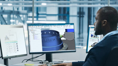
Newer CAM software (see Figure 3) extends this concept to all three-axis finishing operations. In addition to familiar three-axis toolpath user interaction, a few simple, easy-to-understand additional parameters are provided that control the degree and smoothness of tool tilt. The toolpath resembles a traditional fixed axis toolpath. The toolpath processor constantly looks ahead for toolholder collision. When none is encountered, a three-axis toolpath is output. When a potential collision is anticipated, the tool axis is gradually tilted away from the collision area, resulting in a five-axis toolpath.

Figure 3: Siemens PLM Software’s NX CAM can look ahead for potential toolholder collisions and automatically avoids them by tilting the tool.
Summary
With its recent software advances, Siemens PLM Software’s NX CAM helps make the coversion from three-axis and 3+2 axis positioning to simultaneous five-axis machining accessible to everyday NC programmers. Even though some of these techniques might require additional programming time, the benefits of reduced machining, setup time and reduced hand-polishing out-weigh the costs.
Watch a demonstration video showing the NX CAM 3 to 5 axis conversion capability.
Article by:
Edwin Gasparraj, Six Digma LLC
Aaron Frankel, Siemens PLM Software