Vehicle Design Validation | NX Tips and Tricks
Welcome back to another Tips and Tricks installment. This week, our focus is going to be around Vehicle Design Validation (VDV). VDV is a powerful tool that allows you to create realistic simulations of vehicles and their visual devices. In this blog post, we will discuss how to create a new simulation with VDV using a car as an example. You will learn how to:
- Rename a component for easy reference
- Add an eyellipse and set up a standard for the vehicle
- Create features for visualization such as direct vision, mirrors, camera, and rotating pointer
- Make the vehicle an obstruction and the road a grid target
- Create a ground interception and see how the different devices affect the field of view of the driver
Let’s dive in!
Rename a component
The first step is to rename the component that you want to use for the simulation. This will make it easier to reference and understand later on. To do this, go to Vehicle Design Validation and create a new component. Then, right-click on the component name and select “Rename”. You can choose any name that you like, but make sure it is descriptive and relevant.
Add an eyellipse and set up a standard for the vehicle
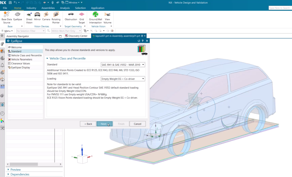
The next step is to add an eyellipse, which is a feature that represents the eyes of the driver. This will help you determine the direct vision of the driver, which is the area that the driver can see without using any visual devices. To add an this into your workspace, select Eyellipse from the menu bar. A dialog box will appear where you can set different standards and loadings for the vehicle. For this example, we will use EG plus co driver as the loading, which means that there are two people in the car. We will also use class A as the vehicle class, which is suitable for passenger cars.
The dialog box will also show you the measurements of the vehicle that are imported from the base data. The base data is the geometry of the car that we added as a component at the beginning. You can customize and change these measurements for different vehicles if you want. For example, you can adjust the head clearance space in the vehicle, which is the distance between the top of the head and the roof. You can also change the display of the eyellipse by choosing different colors and sizes.
Create features for visualization
The third step is to create features for visualization, which are devices that help the driver see better or detect objects around the vehicle. These devices include direct vision, mirrors, camera, and rotating pointer. To create these features, go to Part Navigator and select the device that you want to add.

- Direct vision: This is a feature that shows the area that the driver can see directly without using any devices. To create this view, select Direct Vision from the menu where you can then set up a standard for direct vision that is compliant with your previous standards and your vehicle class.
- Mirrors: These are features that show the area that the driver can see using mirrors on both sides of the car. Once again, select Mirror from the menu. For this example, we will use class 3 mirrors, which are suitable for passenger cars. You also need to select the face of the mirror and the pivot point on your component. The pivot point is where the mirror rotates around its axis. The prime point is where the mirror aligns with the horizon when it is in its default position.
- Camera: This feature shows the area that the driver can see using a camera on the back of the car. You can then select Camera from the menu where you can choose a point on your component where you want to place your camera. You also need to change the direction of your camera lens by dragging it with your mouse. You can adjust the shape and size of your camera view by choosing different parameters such as angle, aspect ratio, resolution, and distortion.
- Rotating pointer: This is a feature that shows the area that a device on top of your car can detect by rotating around its axis. Select Rotating Pointer to choose a point on your component where you want to place your rotating pointer. You also need to make sure that your rotating pointer is slightly above your roof so that it can detect objects around your car more easily. You can adjust the shape and size of your rotating pointer view by choosing different parameters such as angle, radius, and speed.
Make the vehicle an obstruction
The fourth step is to make the vehicle an obstruction and the road a grid target. An obstruction is a feature that blocks the vision of the driver or the devices. A grid target is a feature that shows the area that the driver or the devices can see on the ground. To make the vehicle an obstruction, select Obstruction from the Part Navigator menu. A dialog box will appear where you can select the different bodies that make up your component. These bodies will now obstruct the vision of the driver or the devices. To make the road a grid target, select Grid Target from the same menu bar at the top of the screen. A new dialog box will appear where you can select the direct vision that you saw in the last step. You can also customize and change the loading and the shape of your grid target. For this example, we will use a circle as our grid target shape.
Create a ground interception
The final step is to create a ground interception and see how the different devices affect the field of view of the driver. A ground interception is a feature that shows the intersection of the vision of the driver or the devices and the grid target on the ground. Once Ground Interception is selected, select the features that you want to include in your ground interception. For this example, we will select direct vision, mirrors, camera, and rotating pointer. You can also choose different colors and transparency for your ground interception.
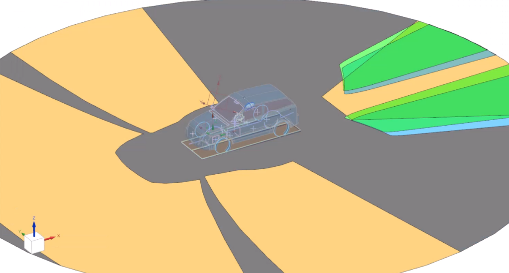
After you create your ground interception, you can see how the different devices affect the field of view of the driver by showing and hiding them on your screen. You can also see how they overlap with each other by changing their order or transparency. You can also see how they relate to the vehicle by showing and hiding the sheet body that was created for it.
To recap….
We hope you have enjoyed this week’s tips and tricks where we learned how to create a new simulation with Vehicle Design Validation using a car as an example. You learned how to:
- Rename a component for easy reference
- Add an eyellipse and set up a standard for the vehicle
- Create features for visualization such as direct vision, mirrors, camera, and rotating pointer
- Make the vehicle an obstruction and the road a grid target
- Create a ground interception and see how the different devices affect the field of view of the driver
Remember to check back each week to find more useful content revolving around NX workflows. We’ll see you next time!

