Topology Optimization part 2 | NX tips and tricks

And here we are with another entry into our NX™ software tips and tricks series. We continue to explore the latest and greatest features added to the December 2022 release of NX. As you can see, this is the second of a two parter, where we are focusing on Topology Optimization within NX. Haven’t seen the first episode? Take a look by clicking on the following YouTube link 👉
Without further ado, lets dive in..
Setting up your study
REMINDER : WHAT IS TOPOLOGY OPTIMIZER?
A generative design solution for designers to lead the product design process from concept to production, converting design requirements and specifications to a manufacturable design
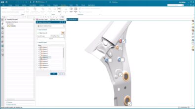
First and foremost, we will be focusing on the linkage body for this specific example; the linkage body will be the design space. When working on a study, you will notice that there are several material options to choose from in the ‘Material List’. The material you select depends completely on the study you are trying to conduct. For the linkage body, we will be selecting steel.
TOP TIP:
Before you start, we recommend renaming the study to something more suitable, as well as ensuring to select the maximize stiffness option in the dialog
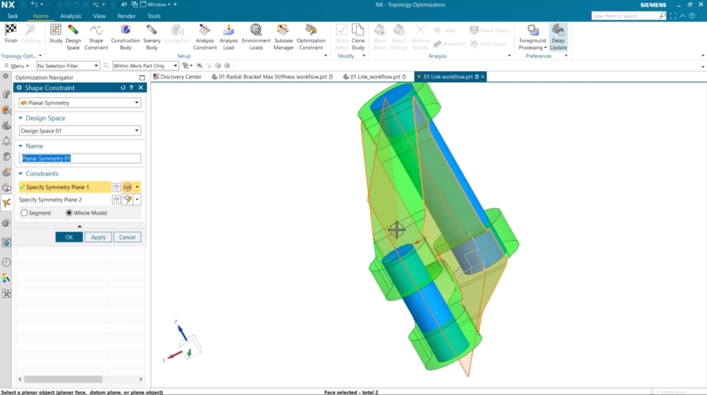
There are a few other important elements to consider at this stage too. For this particular example, ensuring the part is symmetric is important. It’s a small workflow trick to reduce the time taken to create your desired assembly. To do this, in the Topology Optimizer tab in NX, select Shape Constraint, Name your Shape Constraint and select the two faces to create the symmetry. Taking this step adds a planar shape constraint to your part, thus enabling us to move onto the next step.
Creating a Topology Optimization study using added force and load
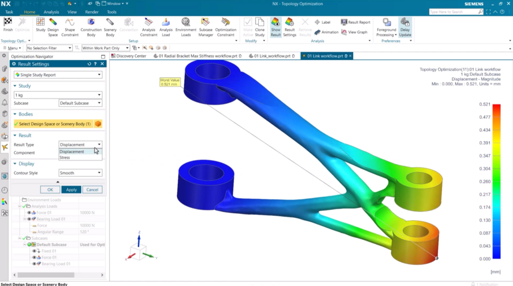
With the planar shape constraint added, we can now focus on further elements for the creation of a topology optimization study. Focusing on the part in question, we need to ensure the two pins are shelled so that they can easily integrate into the assembly. One end of the linkage is fixed and won’t move, whereas the other side has a downwards force of 10,000 newtons, and a bearing load of 10,000 newtons in the Y direction. We ideally don’t want the mass going above 1 kilograms, so we’ve constrained the mass to this value.
This gives us a solid foundation to understand the current displacement and stress of the object, and what needs to be done to improve the part. As things currently stand with a mass constraint, there is considerable stress placed where there the bearing load and downwards force sits.
The approach to take is to keep repeating studies with varying masses so you can get a better understanding of how the stress affects the part.
REMEMBER:
Clone your study so that you conduct multiple stress and displacement studies
Once you’ve cloned your study, you need to increase the accuracy to account for the decrease in member size due to the smaller mass. The only other change that needs to be made is to reduce the mass to 0.8 kilograms. Here’s how to make these changes:
Accuracy
Select Study in your Optimization Navigator dialog box, Name the cloned study to correspond with the new mass and under Solution Balance, move the slider toward the Accuracy option.
Mass Changes
Under the Optimization Constraint option, you’ll find your stored tab for the Max Mass limit. Click into this option and reduce your Max Mass to 0.8kg.
Comparing the stress and displacement tests
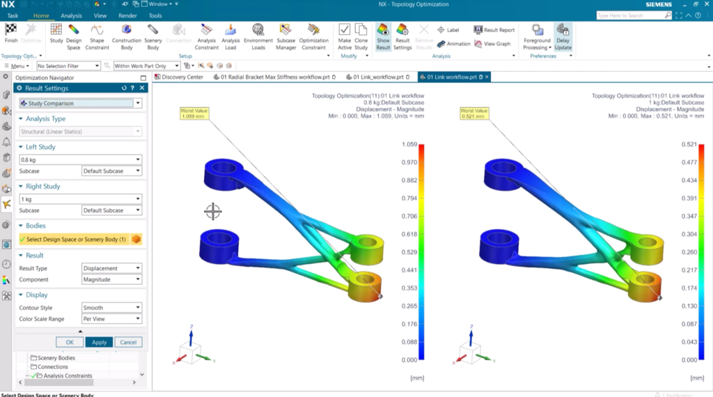
Let’s take a look at the difference between the two stress and displacement tests that have been conducted. We’ll firstly show you how to setup the comparison to be able to compare your different studies. In the Topology Optimization tab, select the Optimize option, close the results graph that appears and click the ‘Results Setting’. In the following dialog box, change the ‘Single Study Report’ option to ‘Study Comparison’ and apply. It’s hugely important to take this step as you’ll start to get an understanding of whether your part is optimal, or whether further studies are required to ensure your part would be fit for purpose. Further optimization maybe required, but that is absolutely not a problem!
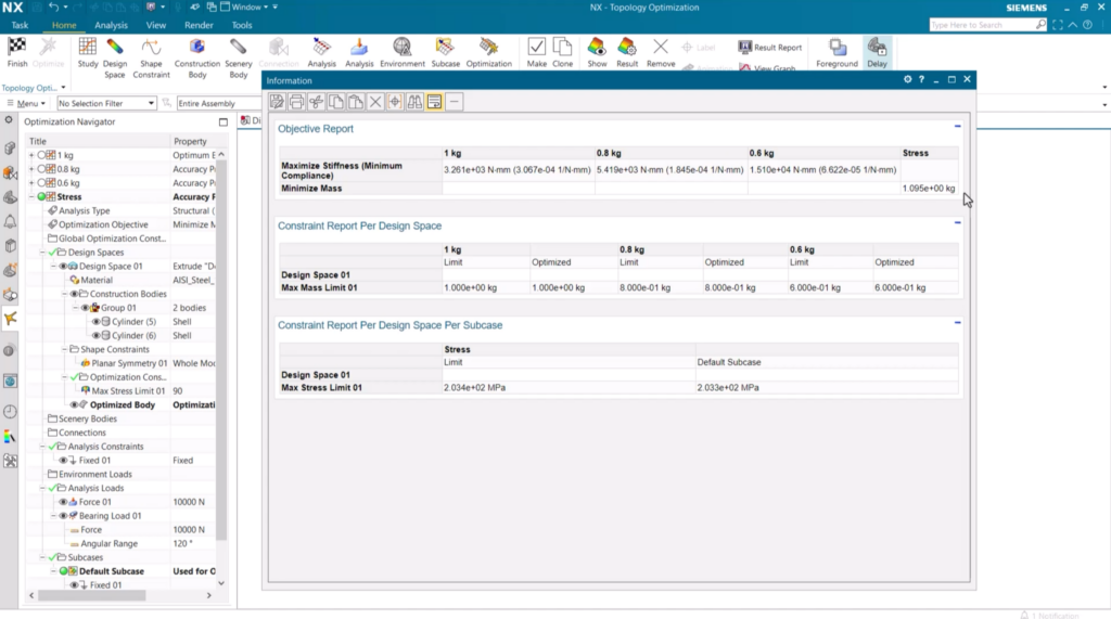
Viewing results in a report
It is also important to utilize the Result Report option within the Topology Optimization study. This is a key tool if there is a need to conduct multiple studies before you settle on the desired constraints. Navigate to the Result Report option in the Topology Optimization tab to see the in-depth summary of your studies. You can see how the stress changes between the stiffness studies, whilst also being able to view the actual mass of the stress study.
Conclusion
And that wraps up the latest episode for this current tips and tricks series! We hope you take key insights and are able to implement into your own workflow. Be sure to check back in the coming weeks for next entries into the series! In the meantime, why not…