Topology Optimization: Part One | NX Tips and Tricks

In an effort to consistently provide you with tips and tricks full of hidden functionality within NX™ software, we are back again with a new installment. If you are new around here, the NX team has been producing new video demonstrations each week to provide learning resources. If you are interested in seeing the full catalogue of tips, you can find those in the NX Design area of the website.
For this series today, we are splitting our tips and tricks around topology optimization into two bitesize chunks to alleviate information overload. We hope you find these useful within your own NX workflow. Let’s have a look, shall we?
Top Tip: Use the Topology Optimization command to start the Topology Optimization task environment, which provides to access a set of commands that lets you optimize material layout within a design space for a set of loads, boundary conditions, and constraints, with the goal of maximizing the performance and shape of a design.
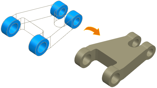
Use topology optimization on several bodies
When you have your bodies loaded into NX and visible in the graphics window, the first step is to use the Topology Optimization command. Using this command allows you to create a study. There are various study types that are available within the Optimization Navigator that can be found within NX. Studies allow you to determine whether the topology if designs can withstand whatever stress they may go through — this could be structural loads or vibrational loads.
Testing for multiple condition states
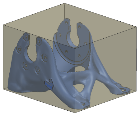
Before running the tests within the study, you need to create a design space. This allows you to select the materials that could be use for optimal design. Within the design space, selecting areas of the model to be kept in or out are essential to the validity of the study.
Before finalizing your study, be sure that you account for all conditions of your model. For example, if there are any moving pieces, such as bolts, these will need to be pinned down for the simulation to be executed properly.
Analyzing the results
Now that the study is finalized, it is time to analyze the results. What we have now is called a mixed convergent body, which is a mesh body with precise geometry included. In order to see how your model responds to applied loads, simply animate the results. This will showcase what areas of the model are subject to the most weight displacement or vibration.
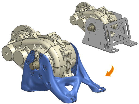
To better visualize the results of your study, it is possible within NX to create a clone study with 3D printing in mind. You may wish to include more details in this design to be more physically accurate.
Topology Optimization: Part One | NX Tips and Tricks YouTube Video
Continue your journey with NX
We hope that you have found this week’s tips and tricks useful! If you are looking for other topic areas to gain more efficiency, remember to check out our entire collections of tips and tricks with the link below!