Topology Optimization: A New Way to Create 3D Designs
As an NX CAD Engineer in Siemens PLM Software, I have worked with my users to build “3D Shape.” This means the intention for “3D Shape” belongs not to me, but to our great NX users or future users.
The users’ intent is shown to me in many ways. Sometimes, it is just in conversation; in many cases, it is with 2D or 3D materials. A pencil drawing, sketch, Adobe Photoshop or Illustrator file, or 2D CAD drawing are all examples of 2D representations, while 3D materials take the form of a scan, STL of clay, polystyrene or chemical wood model, or a 3D IGS model that is not “manufacturable” or “millable.”
These are all a kind of traditional design intent—a way of conveying “3D Shape” information that is thought of and created by humans. Human’s idea, thought, hand or touch goes into each one. Today, we have a new design intent that is created by CAE topology optimization and can be used in the NX modeling application. The CAE parameters are set by an individual – so the user determines the location of a fixed portion of the design, where a pin goes, how much load is applied, the location of pressure or torque, and the directions of each. The “3D Shape” itself though is created by CAE Analysis topology optimization.

Fig.1: A Bike Frame that is extracted from a large design space. The shape looks like a real, existing product in the market. Do we think that topology optimization can create a reasonable shape?

Fig.2: Lightweighted Game Controller keeps the original operability. Original CAD Model on the left, topology optimization result on the right.

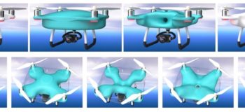
Fig.3: When there is a large free design space, we see more variations created by topology optimization. A few polygon modeling operations are done with original CAD parts. The images above show the different results you get from changing the topology optimization settings.
The output of topology optimization is a JT facet body that can be converted to a convergent facet body. Once that is done, the convergent body can be used with a traditional CAD body. If we need to rebuild the facet body as a normal CAD body instead, we can use NX Reverse Engineering functions to create an exceptionally high quality model in a short time. Thus, we can use topology optimization results in a CAD modeling workflow without any difficulties.
I look forward to seeing how our users will leverage this technology to take advantage of topology optimization results in their designs.

Comments
Leave a Reply
You must be logged in to post a comment.
Topology optimization, as discussed in the Siemens NX blog, revolutionizes 3D design by using computer-aided engineering to define the most efficient material distribution within a design space based on set constraints and loads. This method not only enhances design capabilities but also reduces material waste, leading to lighter and stronger components.
Connecting this to the world of World of Warcraft, imagine if we could apply topology optimization to the design of in-game items, like armor or weapons. These items could be optimized for strength and durability, making gameplay even more immersive and strategic. Speaking of optimizing experiences in WoW, services like Pandaria Remix Boosting offered by Wowvendor (https://wowvendor.com/shop/wow/pandaria-remix/) help players level up their characters and gear efficiently, enhancing their gameplay experience. Just as topology optimization refines a design, boosting services refine your gameplay, ensuring you’re getting the most out of every session.
3D design helps to both reduce the amount of materials spent, find flaws at an earlier stage and, most importantly, make changes at an early stage in order to satisfy the customer. Unfortunately, this trick cannot be implemented in the field of lithography.
As for WoW, you can use 3D design only for figures for such a game, but the quality of such products does not require much attention. But it is very tempting to create real coins from the game, and if you have problems with the currency in the game itself, please contact https://epiccarry.com/wow/boost/gold
Agar.boston is a private server variant of the popular multiplayer game https://agar.boston. Developed by Turkish creators, it offers players an alternative platform to experience the classic cell-eating gameplay with additional features and modifications.
Oh, I remember reading that Siemens post back in 2017 and thinking topology optimization was just some academic exercise, something far from my actual CAD workflow. But then I tried generating a lightweight bracket for a drone project, and the organic shapes that came out of the solver were nothing I could have sketched by hand. That is when I started looking for ways to actually print those bizarre facet bodies, and https://www.gambody.com/ showed me how the gaming community had already solved the problem of turning complex meshes into printable models. The difference is that topology optimization gives you a mathematically perfect bone like structure, but you still need real world printing experience to know where to add supports or split parts. So my advice is treat the optimization result as a suggestion, not a final answer. Reverse engineer it, smooth the harsh corners, and always test a small section first. That bike frame in Figure 1 looks cool, but your slicer will hate those internal cavities unless you clean them up manually.