NX | Tips and Tricks | Mechatronics Concept Designer
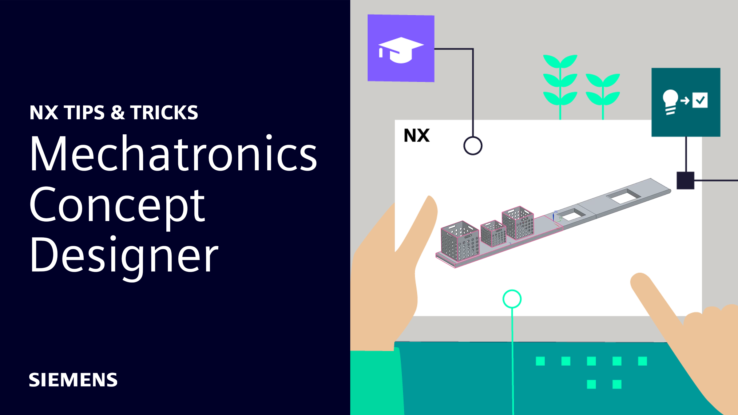
Welcome back to the next installment of our Tips and Tricks series for the June 2024 release of NX™ software. In this blog, we’ll be shining the spotlight on Mechatronics Concept Designer; a tool to easily create and simulate a whole production workflow.
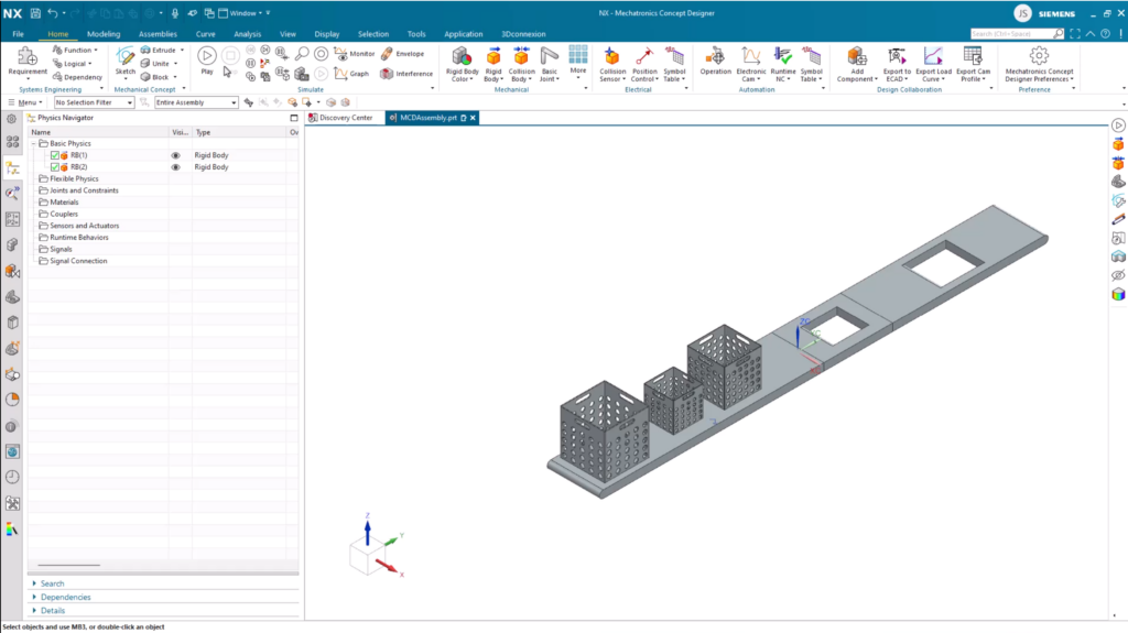
Throughout this tip and trick blog, we’ll be focusing on this production workflow; a basic concept for a system to sort boxes based on their size. Without further ado, let’s dive in.
Creating a mechanical concept
Adding physical behavior to an assembly are the key building blocks to Mechatronics Concept Designer. Adding behaviors will transform a lifeless assembly into a fully operational digital twin of your production line.
Rigid Body
The first place to start is by ensuring items along our production assembly are Rigid Bodies. Without them, objects that will move through a production assembly will stay static. Let’s go ahead and apply Rigid Bodies to the boxes in this use case.
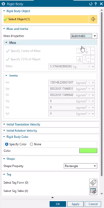
The feature can be accessed under the Mechanical tab. From there, you’ll be able to define specific properties for your Rigid Bodies. From here, you’ll be able to edit the mass of the objects in question, as well as the inertia properties. Additionally, you’ll also be able to edit the initial translation and rotational velocity of your objects; setting these will let you control whether your objects stay stationary at the start of your simulation.
Collision Bodies
At this stage, if we were to run the simulation, instead of the objects staying still, they would fall through the conveyor belt. So the next step is to add Collision Bodies for both the conveyor, and in this case the three boxes.
Setting up Collision Bodies for the first selection of the conveyor and the three boxes is a little more straightforward. Simply select the Solid Body option for each element, click the Box option as the Collision Shape, and Apply the changes.
Setting up Collision Bodies for the two sections of the conveyor with holes is slightly different. Instead of selecting the Solid Body option, choose the Face option, and then select any faces that the boxes will come into contact with.
Additionally, the Collision Shape needs to be Mesh in this instance, otherwise the collision body will not appropriately represent the hole in the animation.
Adding motion through transport surfaces
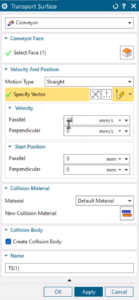
If we clicked play on the simulation at this stage, the boxes now rest on the conveyor, but do not move. So the next step is to add transport surfaces to the conveyor belt. These can be accessed from the Sensors and Actuators folder in the Physics navigator.
From here, it’s as simple as altering the properties until you’re happy. The default option is the Conveyor option, so there’s nothing to change here. Additionally, you’ll be able to change the speed of your conveyor using the Velocity option.
Continue your journey with NX
That’s another Tips and Tricks blog complete. We hope you’ve taken some handy tips from this post on how to use Mechatronics Concept Designer. Be sure to check out the NX Design blog to learn more.
