Electro-Mechanical Routing | What’s New in Designcenter NX | December 2025 Release
We are continuing our journey through the What’s New in Designcenter™ NX™ software blog series with highlights from the December 2025 release—this time focusing on Electro-Mechanical Routing.
This release delivers capabilities that address the unique challenges of routing cables, wires, and harnesses through complex assemblies. Designcenter NX differs from other solutions as it provides a complete comprehensive digital twin approach that connects:
- Electrical Diagrams
- Cable Routing Analysis
- Physical Tray placement
Automated Cable Tray placement: From manual layout to intelligent automation
Cable tray routing has traditionally required tedious manual placement of individual tray segments, careful measurement of gaps, and constant verification that tray widths match space reservations. The new Place Cable Trays function transforms this workflow with intelligent automation.
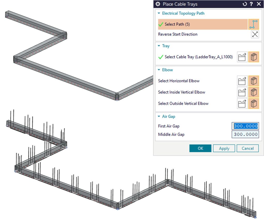
The capability places multiple trays on an Electrical Topology Path (ETP) with space reservations in a single operation. Trays are automatically positioned with specified gaps, resized to match space reservation widths, and optionally include elbows at direction changes. The parts remain linked to space reservations, so updates automatically propagate to the trays—eliminating manual rework when design changes occur.
This automation works seamlessly with NX Cable Router, which determines optimal tray widths based on routed cables. The result is a closed-loop workflow where cable routing informs tray sizing, and tray geometry updates automatically as cable fills change.
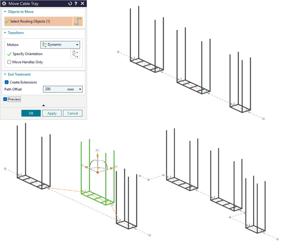
Dynamic Cable Tray movement: Collision avoidance without starting over
Design changes are inevitable, and discovering that a cable tray interferes with newly added equipment often meant manually subdividing paths, creating offset segments, and repositioning multiple components. The Move Cable Tray function addresses this with intelligent automation.
The capability enables easy movement of one or more trays to avoid collisions, while automatically subdividing the Electrical Topology Path as needed. It can optionally create additional segments with offsets for squared paths, maintaining proper routing geometry without manual path editing. This improvement combines several tasks into a single step, significantly improving productivity.
The function includes intelligent controls for different scenarios. When placing trays like hangers that don’t split the path, designers can clear a preference to prevent automatic path subdivision, ensuring the automation adapts to different design intents.
Fill Rule and Segregation Override: Flexibility within standards
Electrical codes and company standards often require segregation of power, control, and instrumentation cables to prevent interference and maintain safety. Fill rules and segregations are typically preconfigured on cableway patterns to enforce these requirements automatically. But real-world designs sometimes require exceptions.
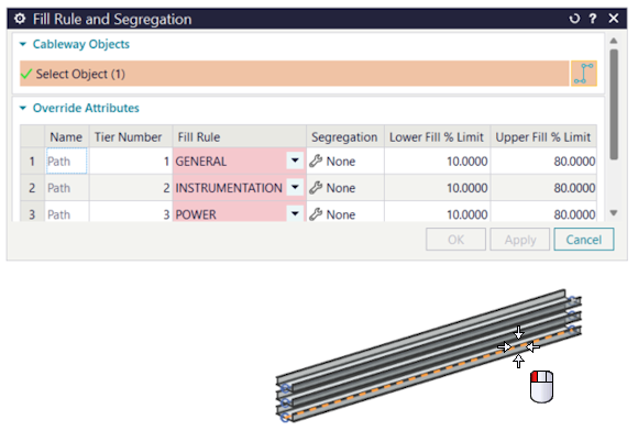
The new Fill Rule and Segregation Override capability provides controlled flexibility within this structured environment. Designers can override default fill rules and segregations for all tiers when engineering judgment requires it, while administrators can restrict this capability through customer defaults to maintain governance. This balance between flexibility and control is essential in industries where electrical safety is critical but design exceptions are sometimes necessary.
Enhanced alignment options: Precision placement for complex geometries
Routing electrical components through congested spaces requires precise control over part placement. The enhanced alignment options in Place Part, Edit Placement, and Edit Path provide the control engineers need for complex routing scenarios.
The capability projects a reference point onto the routing path for controlled, precise part location. Reference points can be projected by minimum distance or along XY, YZ, or XZ planes, with optional offsets to stagger positions precisely. The reference point maps to the active dimension, providing clear feedback on placement geometry.
This projection-based approach offers a clearer, more effective workflow than previous methods, eliminating guesswork and reducing iteration cycles needed to achieve correct placement.
Flow direction alignment: Maintaining design intent from diagram to 3D
Modern electrical design workflows often begin with 2D diagrams that establish system architecture and flow direction before 3D routing begins. NX Diagramming supports flow direction on 2D symbols, and Routed System Designer uses this information to place parts in 3D with correct flow direction. But what happens when parts are placed before flow direction is established, or when flow direction changes on the diagramming side?
The Flow Direction Alignment improvement addresses this with the ability to correct parts that are not aligned with flow direction. Available through the Run and Branch nodes in the Run Navigator, this capability ensures that 3D routing remains consistent with design intent established in diagrams.
This capability strengthens the connection between 2D electrical diagrams and 3D routing models, ensuring that design intent flows through the entire development process.
The integrated workflow advantage
By combining multiple tasks into single automated steps—such as moving cable trays while automatically subdividing paths and avoiding collisions—these productivity enhancements eliminate repetitive manual steps, allowing engineering teams to focus on design intent rather than tedious layout tasks.
These capabilities work together to support modern electro-mechanical routing workflows. You might begin with diagrams that establish flow direction and system architecture, then use automated cable tray placement to quickly create physical routing that respects space constraints.
As the design evolves, the Move Cable Tray function handles geometry updates automatically. Enhanced alignment options provide the precision needed for connector placement, while fill rule overrides offer controlled flexibility when standard patterns don’t fit specific situations.
The Teamcenter® software integration ensures that routing designs, fill rule configurations, and segregation requirements are managed and accessible across entire teams. This integration between disciplines and between 2D and 3D environments reflects how electro-mechanical design actually happens in modern product development.
The December 2025 release represents a vision of routing without artificial barriers—where automation handles repetitive tasks, intelligent tools adapt to design changes, and workflows connect seamlessly from diagram to detailed 3D routing.
Ready to explore these capabilities? Contact your Siemens representative to learn how Designcenter NX 2512 can accelerate your electro-mechanical routing workflows.
Take me to the full Designcenter NX blog 📚