DesigncenterNX | How to series | Sheet Metal
In our latest Designcenter NX™ software How to series video, we explore the end-to-end process of designing a sheet metal bracket within the application Designcenter NX Sheet Metal. Leveraging this powerful application empowers users to achieve faster design iterations, ensure precise fabrication, minimize errors, and allows you to bring innovative sheet metal products to market with unmatched speed and reliability. Below, we’ll demonstrate how to use Designcenter NX Sheet Metal to create a bike seat bracket.
Check out the video below or scroll down to learn more.
What is Designcenter NX Sheet Metal?
Designcenter NX Sheet Metal is a specialized application within the Siemens Designenter NX software suite, purpose-built for the efficient and accurate design of sheet metal components. It provides a comprehensive set of tools that not only enable the creation of complex 3D sheet metal geometries, but also intelligently generate precise, manufacturable flat patterns. Its core strength lies in its associativity, meaning any change to the 3D model automatically updates the flat pattern and associated manufacturing information, ensuring designs are always production-ready, reducing errors, and accelerating the entire product development cycle.
Designcenter NX Sheet Metal design process: Step 1 with Tabs and Flanges
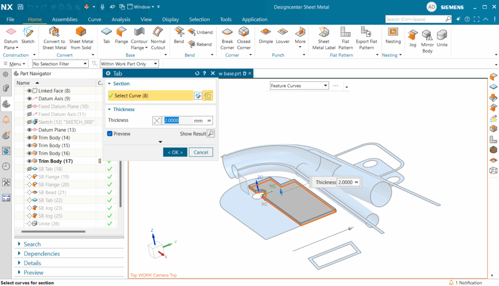
Our design process commences by establishing a tab on the primary frame of our reference geometry. Designcenter NX streamlines this initial step. Upon selection, we leverage the Project Curves command a vital tool that allows us to precisely extract geometry from our references. This ensures impeccable alignment and accurate sizing for our new features. With the necessary curves defined, we then employ the line tool and the trim tool to swiftly sketch our tab, all to guarantee design intent. Once the sketch is complete, a quick confirmation of our desired 2mm thickness in the tab dialog box is all it takes to generate our foundational element.

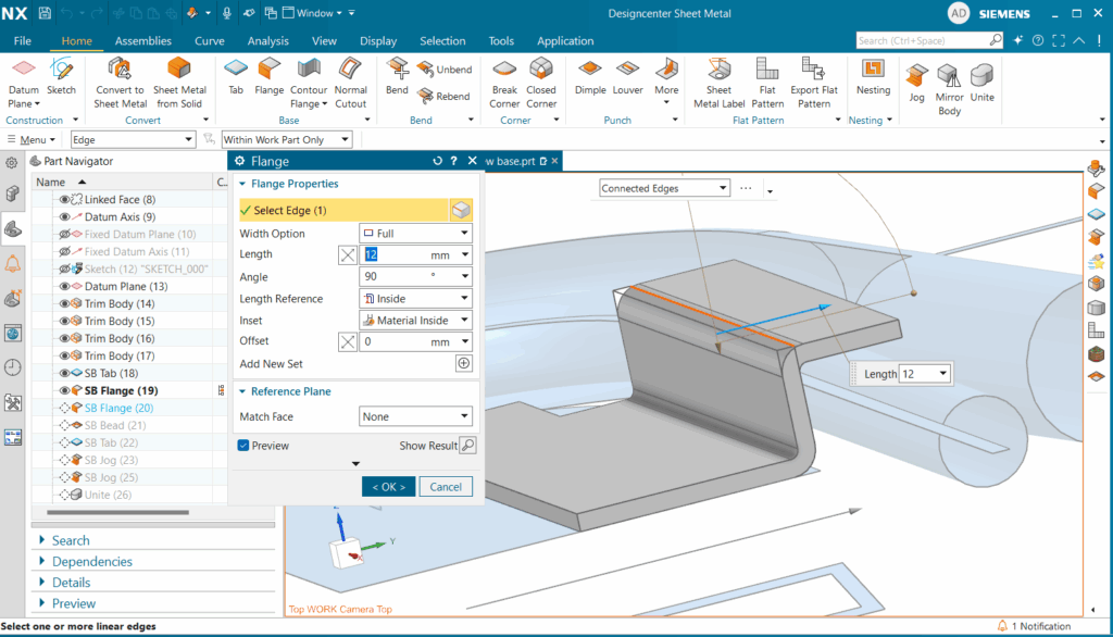
Transitioning seamlessly, we then utilize the flange command to rapidly introduce two 12mm flanges. The beauty here lies in its simplicity: a mere selection of the desired edges prompts Designcenter NX to generate these features instantly. A crucial final check confirms that these new flanges closely conform to, yet do not interfere with, our existing reference geometry.
Designcenter NX Sheet Metal design process: Step 2: Increasing Strength and Integrity with Beads
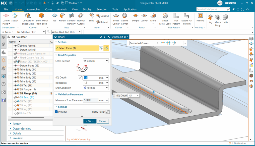
With our flanges in place, the next step involves integrating a bead onto the base tab. Beads are fundamental to enhancing the stiffness, structural integrity, and overall robustness of sheet metal components, often allowing for material optimization without compromising performance.
While our example will feature a straightforward linear bead although they can be made with many turns twists, Designcenter NX offers extensive customization. Users can precisely define the bead’s cross-section from options like circular, U-shaped, and V-shaped, alongside versatile end conditions such as formed, punched, and lanced. For our demonstration, we’ll adhere to the circular and formed settings, specifying a depth and radius of 1.5mm. This level of control ensures beads are tailored to specific design requirements.
Standout feature in Designcenter NX Sheet Metal: flat patterns
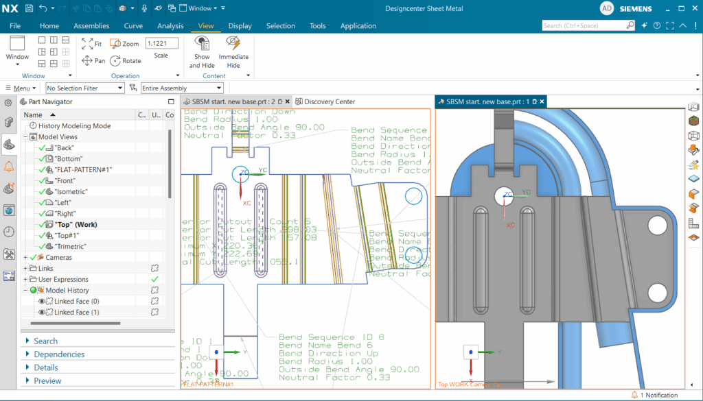
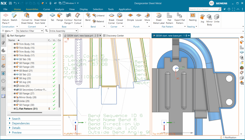
A standout feature of Designcenter NX Sheet Metal is its ability to simultaneously display both the 3D model and its flat pattern. By opening a new window and engaging the split-screen functionality, designers gain an immediate, profound understanding of manufacturability and real time visual confirmation of flat pattern accuracy.
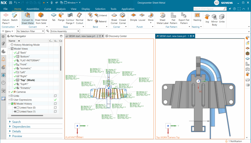
To illustrate this, we can add new flanges to our 3D model. As these modifications are made, the flat pattern in the adjacent window dynamically updates. This live associativity empowers users to continuously refine their designs, instantly observing the impact on the unfolded geometry, thereby streamlining iterations and significantly reducing potential errors. Once our demonstration of this powerful feature concludes, we’ll close the flat pattern window and revert our model to continue with the next design phase.
Advanced Tabs and Jogs
As our design journey continues with the creation of another tab, intended to wrap around a circular section of our reference geometry. Again, we initiate the sketch using Project Curves to capture all necessary geometric references. The extend command then seamlessly connects our curves, followed by trimming to finalize a clean, complete sketch.
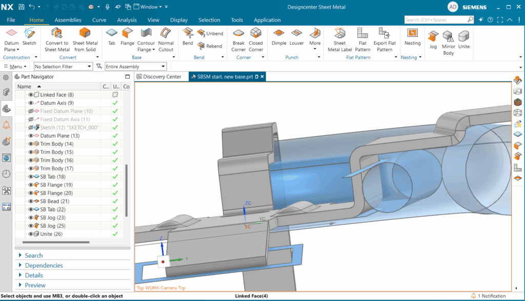
Upon completing the sketch, we ensure the tab is designated as a base feature and its direction is reversed to align flush with our existing sheet metal. However, after creation, we observe an interference between our bracket and the reference geometry a common challenge in intricate designs.
To precisely resolve this, we introduce the jog command. A jog creates a controlled offset, allowing the sheet metal to neatly bypass obstructions. Similar to creating tabs, we define the jog line using Project Curves, ensuring it provides ample clearance. We set its height to 1.5mm, reverse its direction to match our bracket’s orientation, and confirm that the height reference is internal with material inserted externally. This results in a snug, non-intersecting fit. We then replicate this process for a second jog line, guaranteeing perfect flushness with the reference geometry.

Contour Flanges and Unifying Components
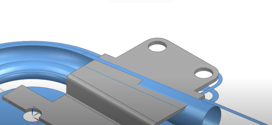
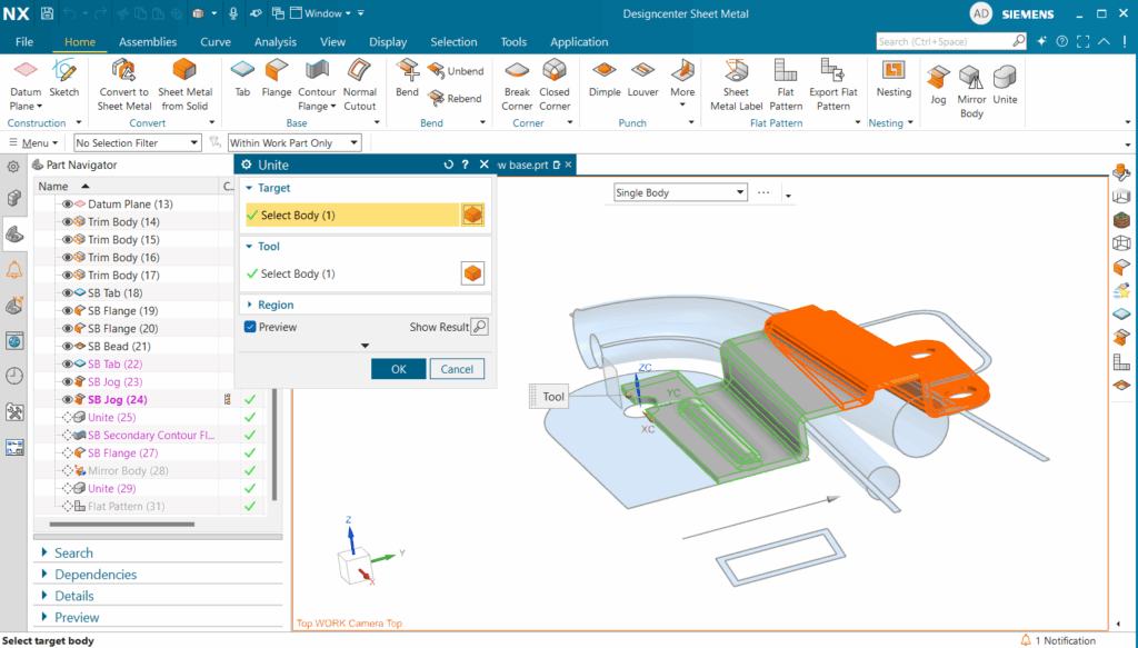
With the second jog precisely positioned, our sheet metal bracket now gracefully conforms to the reference geometry. To consolidate our design into a single, cohesive entity, we employ the unite command, merging our two separate bodies into one a crucial step for subsequent manufacturing and analysis.
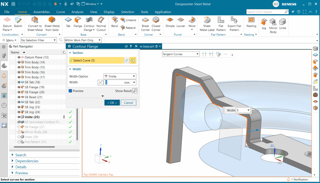
Next, we leverage the contour flange command to form sheet metal around the frontal tubes. This involves selecting a reference edge, orienting the normal plane to align with our center plane, and then freely sketching the desired contour. We can then interactively adjust the sketch to achieve a flush fit with the reference geometry. Once finalized, a contour flange of our sketch is generated with a specified width of 5mm.
To complete the backside of our bracket, we add a final flange. Within the flange dialog box, we set the width option to at end, the match face to until selected, the length to 25mm, and the inset material to outside. This allows us to create a precisely defined flange from a selected edge to a specific face. With this final step we successfully created half of a sheet metal bracket that we could then follow up with mirroring our sheet metal body and uniting it all as one.
Creating Drawing Sheet of Flat Pattern
The concluding step involves generating a comprehensive drawing of our model, specifically showcasing the flat pattern to convey all necessary manufacturing information. We initiate a new drawing, select the appropriate sheet size, and critically, link it to our model by ensuring the name matches in the ‘part to create a drawing of’ dropdown.
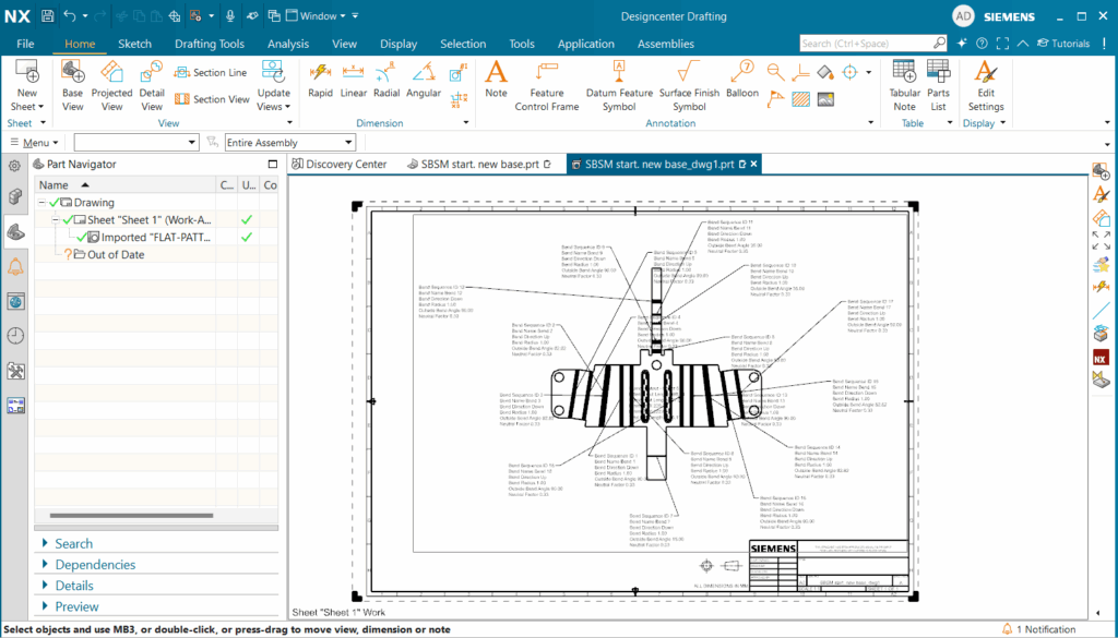
Upon creation, a dialog box facilitates populating the title block. We can then easily place standard base views of our model. However, for manufacturing, our focus is on the flat pattern. We select ‘base view’ and then ‘flat pattern’ from the model view dropdown.
Initially, you might observe that the PMI (Product Manufacturing Information) doesn’t automatically transfer. To rectify this, we navigate to File > Preferences > Drafting > Flat Pattern View > PMI, and activate inherit flat pattern PMI. After applying these changes and re-placing our flat pattern view with PMI enabled in its settings, all our critical manufacturing PMI populates, ready for precise arrangement and annotation.
Summary of Sheet Metal
Throughout this comprehensive guide, we’ve journeyed through the end-to-end process of designing a complex sheet metal bracket within Siemens Designcenter NX. We began with foundational features like tabs and flanges, progressed to enhancing part integrity with beads, and expertly managed intricate geometry using jogs and contour flanges.
Crucially, we demonstrated the transformative power of the associative flat pattern feature, emphasizing the immense value of side-by-side visualization for immediate design validation and manufacturability assessment. We also explored highly efficient techniques such as uniting and mirroring bodies, culminating in the generation of a complete manufacturing drawing replete with all necessary PMI.
Ultimately, Designcenter NX Sheet Metal stands as a paramount tool, empowering you to achieve accelerated design iterations, guarantee precise fabrication, drastically minimize errors, and confidently bring your innovative sheet metal products to market with unmatched speed and unwavering reliability. It streamlines complex challenges, enabling you to work smarter, not harder, while maintaining absolute mastery over your design process.