What’s new in Valor NPI 2510

The Valor NPI 2510 release brings additional checks, better manufacturing awareness and exciting visual enhancements that show a significant evolution of the product offering. Valor NPI’s 3D view has been reimagined to make exploring Design for Manufacturing (DFM) results intuitive and precise.
3D viewer
The 3D Viewer will fundamentally change how several DFM reviews are performed. While the majority of checks will still be done in the standard 2D environment, the all new 3D viewer allows for immersive and intuitive inspections that will quickly become the norm. The 3D viewer allows users to measure distances directly in the 3D space, clarifies embedded component layer placement, and aids in alternate component visualization.
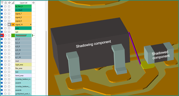
The enhanced 3D environment also now displays embedded components and flex-region parts on their specific placement layers. This layered visualization faithfully reflects rigid-flex board designs, improving overall understanding and communication across teams.
Alternate VPL packages and manufacturer compatibility review
Managing alternative parts has been simplified with Valor Parts Library (VPL) number matching and 3D visualization. Designers can seamlessly switch between various VPL packages for a given component and instantly review the compatibility of alternate manufacturer parts with copper pads within the 3D visualization. Components are presented on their accurate placement layers, ensuring context-aware verification and streamlined decision-making.
Advanced rigid-flex analysis with LPI support
Rigid-flex PCB manufacturing poses unique challenges, especially around solder mask application in flexible areas. Valor NPI 2510 includes new checks on both coverlay and Liquid Photo-Imageable (LPI) solder mask on flexible regions. This analysis validates any manufacturing constraints related to using solder mask in flex areas and includes:
- Drilled mask defined pads
- Undrilled mask defined pads
- Solder mask clearance for non-mask defined drilled pads
- Solder mask clearance for non-mask defined undrilled pads
- Minimum coverlay and LPI overlap
In addition, the rigid flex constraints for Valor NPI have been greatly improved in both 2504 as well as this 2510 release. Valor NPI 2510 has seen checks added for:
- Coverlay overlap for mask defined drilled pads
- Coverlay overlap for mask defined undrilled pads
- Coverlay clearance for non-mask defined drilled pads
- Coverlay clearance for non-mask defined undrilled pads
- Line width changes close to stiffener edge
- Line width change outside bend area
- Line direction change outside bend area
- Opposite-side coverlay coverage for toeprint
- Stiffener support to component NSMD pad
- Stiffener support to component SMD toeprint
- Board outline radius
- Clearance for routing and cutting path
- Silk screen distance to bend area
IPC-compliant solder paste and stencil checks
Valor NPI 2510 has fine-tuned the default values to align more closely with IPC-7525 standards for solder paste and stencil aperture ratio and area ratio. Typically, a traditional process requires an area ratio greater than 0.66 and an aspect ratio greater than 1.5, but it varies with the stencil technology and solder paste particle size. This helps to ensure proper solder paste coverage. Users can specify different aspect ratio requirements tailored to the package type, making quality control more precise and aligned with industry standards.
Intelligent copper area calculation for optimal board reliability
Balanced copper distribution in PCBs minimizes warping, boosts reliability, and ensures electrical consistency. Valor NPI 2510 enhances the matrix with integrated copper area calculation and a copper distribution map, streamlining access and visibility.
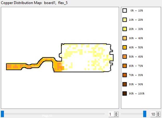
This distribution map complements traditional feature views to aid immediate detection of unbalance risks. This heatmap gives engineers real-time insights to optimize layouts for mechanical stability and electrical performance.
Validating multiple pin lengths in a single through-hole (TH) component
Valor NPI 2510 retrieves pin lengths from different pin groups of a VPL package, allowing multiple pin lengths to be validated for a single TH component.
VPL pin groups with varying pin lengths are reported individually. This enhances the accuracy of pin length checks, ensuring that distinct pin groups are properly analyzed during DFM validation. The pin length retrieved from the VPL is given higher priority than the value specified in the “Pin Length” attribute
Cadence advanced degassing shapes
Advanced degassing shapes generated in Cadence are available with translation to ODB++. These include:
- Circle
- Octagon
- Square
- Oblong (x/y)
- Hexagon (x/y)
- Rectangle
Try Valor NPI 2510
Valor NPI 2510 marks a significant step forward in the fusion of design and manufacturing with advanced 3D visualization. Explore the full capabilities of Valor NPI 2510 and experience a smarter, more confident approach to Design for Manufacturing.