How PADS Professional Can Help You Flex!
As I wrote in my last blog, ‘When to flex?’, flex and rigid-flex are becoming increasingly popular in PCB design. But what are some of the things you should look for when choosing a flex design tool?
First, you need a flex-aware tool that enables easy and intuitive assembly definition. With PADS Professional you can quickly define unique stackup objects, such as stiffeners and cover layers, and change stackups by board outline. This means flex cables can overlap as long as they are not on the same layer. Don’t worry about defining flex overlap sections; simply define the individual board outlines. If you already have a board outline, you can import it directly from your mechanical CAD tool.
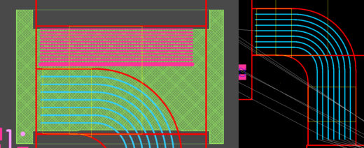
Second, you want a tool that can speed up the definition of critical rigid and flex interfaces. In other words, if it’s not fast, why bother? PADS Professional has unique capabilities for accelerating flex layout and routing such as curved routing, shape-based via placement, dynamic copper pours, curved teardops, and shaped-based hug route.
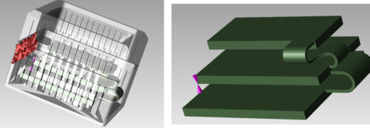
Obviously, manufacturability is another key element in flex design. No problem! With PADS Professional, you work in a 2D/3D design environment that makes visualization easy. Define where and how the design will bend using flex-specific drawing objects to create bend areas.
Then apply correct-by-construction keepouts – with associated constraints – to those bend areas and review the board with a comprehensive checklist of flex-aware design rules to ensure electrical performance. With PADS Professional, you can increase both manufacturability and reliability.
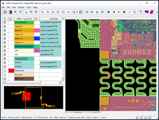
Ambiguity in manufacturing output is further eliminated by ODB++ which differentiate between flex and rigid sections and support flex-aware objects like cover layers and flex bend areas (red).
With ODB++, you can export a step model of the entire PCB and open it in your mechanical tool of choice for PCB enclosure co-design.
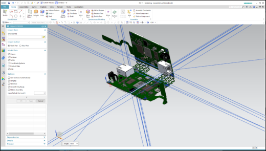
Import an assembly directly into the 3D view to verify clearances, component placement, and the interface between PCB and assembly. Verify complex bend areas to make sure that your origami-like circuit is correctly bent.
All these features in a design tool help to formalize and speed up the flex design process. The correct-by-construction design minimizes board re-spins. I talk about this in my latest webinar, Why you should consider rigid-flex in your next PCB design.


