Several Phenomena can Cause DDR Signals to Behave Badly
Often, either the setup or hold time margin may be very low. If setup is low while hold time is high, then it’s likely that the strobe (or clock) is not well-aligned with the DQ (or address). In such cases, the remedy is often within the feature-set of the controller. If the controller permits a delay-calibration of each individual bit, the simulation can be redone with the appropriate delays for the signal bits. (HyperLynx® does this automatically.) If the controller does not support calibration of each bit, then some of the signal bits might need a larger or smaller electrical delay while routing. Be sure to take the controller’s package propagation delays into account when simulating.
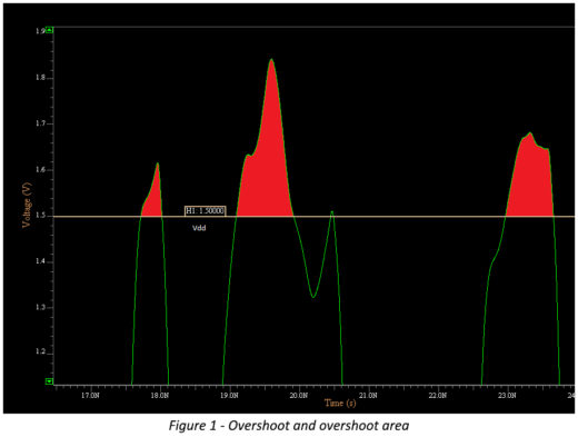
Another common cause of DDR bus failure is excessive ringing (Figure 1). This is often caused by improper termination. Ringing can cause violations of multiple JEDEC requirements, including excessive maximum overshoot, excessive overshoot area, or setup/hold timing. Some violations, such as overshoot, can damage the chips. This damage might not always occur on the first bring-up, but rather might happen over a longer duration of time after repeated violations. Knowing about such violations early on can save significant costs down the line often by simply trying different ODT settings at the receiver until the ringing comes down to an acceptable level.
A third common issue is excessive noise on the signals. This can happen when too much crosstalk energy is injected into a signal from a nearby switching signal. This can be fixed by separating the signals spatially from each other.
Another common issue is the presence of stubs in the channel. Stubs that cause reflections often look like “steps” in the waveform. If the stubs can be shortened, such as with test points, signal integrity will be improved. Often, the step seen in the waveform is because the measurement was made on read transactions at the pin of the controller. This can quickly be remedied by shifting the point of measurement at the controller to the die instead of the pin. This measurement issue is caused because the IBIS file for the controller often does not explicitly call out a measurement at the die.
Find quick solutions to overshoot and ringback issues caused by reflections in this short video.