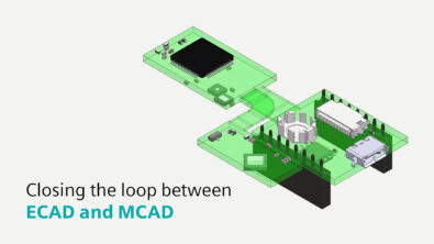
Defining Collaboration between Electrical and Mechanical Domains
Modern electro-mechanical designs have many design challenges that cause various obstacles throughout the design process. Typically these challenges can be separated into two major groups:
- Collisions due to component and mechanical clearances not being accounted for
- Synchronization of design data between both electrical and mechanical designs
In the past, designers often had to exchange emails back and forth to truly understand the other designer’s intent. The process was cumbersome and often information was lost or there were large periods where no information was exchanged by the designers. Therefore, designers often had violations that caused issues downstream. As a result, designers spent a significant amount of time re-working the design to ensure that the overall design met the design requirements before the final signoff.
With the introduction of the ProSTEP format (IDX), tight synchronization between the electrical and mechanical flows is possible and very easy. Designers can easily collaborate with each domain at any frequency throughout the design process. They can exchange the true design intent to ensure that all mechanical and component clearances are enforced at every stage of the design.
What must change to make this synchronization successful? With this more powerful technology comes more responsibility in defining the flow in which information is exchanged. Defining a design flow is critical in enabling an efficient process. The time invested in this stage reduces redundant steps and ensures that correct data is exchanged and enforced throughout the project.
In most electro-mechanical projects, critical design constraints are first defined by the mechanical engineer, including board outline, mounting hole locations, placement/routing keep-out areas, connector placement, etc. The design requirements and board elements are then exchanged with the ECAD designer to ensure that the correct information is used to start the project.
The initial exchange is the ‘Baseline’ file and is the same as if you were using IDF as it will contain the entire assembly database from the mechanical domain. However, that is the only similarity between the two. The new ProSTEP iViP schema now allows you to go beyond sending a single, static file to/from each design team because it allows each domain to send incremental data (ie: only what changed, after the initial ‘Baseline’ exchange).
As you can imagine, this facilitates a much more consistent and accurate flow of information back and forth between design disciplines as it also provides a report of the differences, a way to include notes about what changed directly in the IDX file itself, and the ability to graphically interrogate the updates on the PCB or mechanical assembly and accept or reject them. This process fosters closer collaboration and enables early identification of critical issues during the design flow.
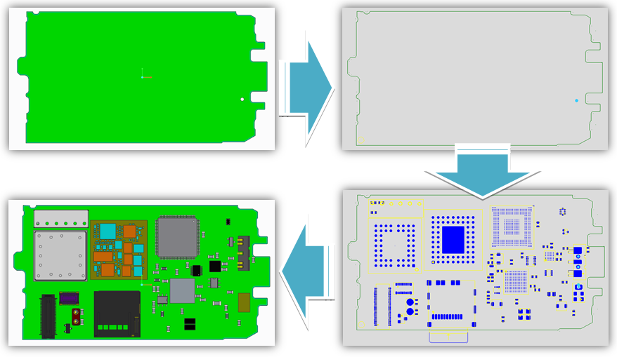
The following steps outline a typical workflow between ECAD and MCAD design tools using the ProSTEP iViP schema:
- The mechanical engineer creates a PCB inside an assembly that mounts to existing hardware.
- A ‘Baseline’ IDX file is exported to the ECAD designer.
- The ‘Baseline’ is accepted in the ECAD design, synchronizing the ECAD with the MCAD databases.
- The ECAD designer then sends back a ‘Response’ file to the MCAD engineer that the ‘Baseline’ has been accepted.
- The board is modified in either the MCAD or ECAD tool suite and sent to the respective tool using a proposal (incremental) collaboration file.
- The ECAD designer (or MCAD engineer) then reviews the updates and either accepts or rejects the proposal and sends a response file back to the originator.
- The second designer/engineer accepts the ‘Response’ file and the process continues.
With a defined workflow in the ProSTEP exchange, you will be able to identify electromechanical issues before it is too late and have more time for other projects.
Check out one example of an electro-mechanical collaboration with PTC Creo and Mentor Graphics Xpedition® in this white paper: Optimizing Electro-mechanical Collaboration. You also might be interested in my previous blog post on this topic: Tired of writing stick it notes and emails to collaborate on your electro-mechanical design?
For additional information on MCAD collaboration, visit this page. If you are using the ProSTEP protocol in your process, let me know what you think in the comments below.