PCB Routing Solutions: Simplifying the Tuning Process – Part 2 Manual Tuning
When tuning a set of nets in Xpedition Layout, there are methods to do it automatically or manually – or both. The previous post in this routing series explored the use of Auto Tune and the Target Lengths dialog. In this post, we will look at the manual tuning features and the options available for using them in a productive manner. The intent here is to reveal the new capabilities in the context of the existing ones.
Discovering What Needs to be Tuned
Normally designers will focus on resolving routing timing challenges circuit by circuit, interface by interface. Discovering what needs to be tuned is just a reflection of knowing the circuit and proceeding to adjust the lengths to follow the rules. However sometimes – especially at the end of the design process, it is good to review all the nets to be tuned and determine if they fulfill the rules. There are a number of enhancements for doing this in Xpedition Layout, and each one has its own value.
Net Explorer:
This dialog automatically organizes the nets that have rules assigned in CES into groups. The Tuned Nets group lists all the nets that have delay rules that can be resolved by tuning. The Matched Length group lists each matched length set as defined in CES, and organizes them by the user defined ID. This is a quick way to see which nets have tuning requirements. Using other features like Cross-probing and Marking allows you to easily find and isolate them in the graphics window. When a net or group of nets are marked, you have options in Display Control to display just the netlines for those nets.

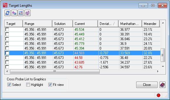
Target Lengths:
In my previous post, this dialog was described in some detail. In the context of manual tuning, the best thing is that you can see which nets still need to be tuned in a given cluster; and the fact that it is updated dynamically as you modify lengths in the graphics.
Tuning Meter:
Using the Tuning Meter is the best way to get instant feedback on length adjustments. The Target Lengths dialog is dynamic; however, it is not as instant as the Tuning Meter which is updated with even the smallest movement of the cursor. As you drag on a segment or the pattern box, the tuning meter will tell you exactly where you are within the range defined by the tolerance. It works when making Phase Matching adjustments as well.
Hazards:
The Hazards dialog provides a way to find any remaining nets that need to be tuned. This is especially useful when at the end of the design when you want to find any last remaining tuning that is needed.
- Differential Pair Length and Phase Matching – The Hazards dialog is the only way to find the nets that still need length or phase matching to fulfill the CES rules. Once you find a hazard for diff pair length tolerance or phase matching, you can select the Resolve button which will add a sawtooth or uncoupled pattern to automatically adjust the length to remove the hazard.


Adding Manual Tuning Patterns
There are a number of different ways to add tuning patterns and it is important to control what the initial pattern looks like when doing so. Selecting one of the toolbar icons is a very quick way to add a pattern.
Tuning Dialog:
When a tuning pattern is added, it follows the rules setup in the Tuning dialog. You can modify it after it is added, but the initial pattern style is controlled by this dialog.

Manual Tune Icon:

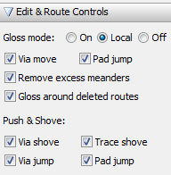
When you select a trace, this icon becomes sensitive and when pressed, it will add a tuning pattern that obeys the rules setup in the Tuning dialog and it will obey the Push and Shove settings in the Editor Control dialog. If you don’t want the new tuning pattern to disturb existing routing, turn Trace Shove off. When the tuning pattern is added, it also obeys the other Push & Shove settings, including Via Shove, Via Jump and Pad Jump.
- With Trace Shove Off:

- With Trace Shove On:
Interactive Tune:

If you select the Interactive Tune icon, the dialog will open. In previous releases, this feature was part of the Smart Utilities but now it is included in the standard Tune Routes functions. The general methodology is to define the tuning parameters and when you click “Tune” you can then select a trace to add that tuning pattern.

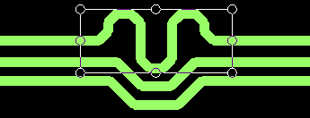
Sawtooth:

Adding a sawtooth pattern is a new capability in Xpedition Layout. It is used for diff pair balancing to fulfill either the Differential Pair Tolerance (length matching) or the Differential Pair Phase Tolerance (phase matching) rules set in CES.
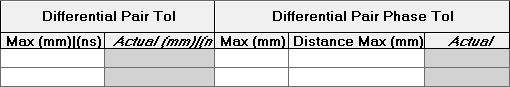
The Differential Pair Tolerance rule defines the allowable length or delay difference for the total length of the differential pair routing.
The Differential Pair Phase Tolerance is expressed by two values: First, the maximum tolerance, and second the maximum distance for that tolerance to be applied. For example, you can say that a tolerance of .24mm is allowed over a distance of 12mm. That means that as you traverse the route from source to load, for each 12mm of distance, the diff pair compliments must have lengths within the .25mm tolerance.
In the Tuning dialog, you define the parameters for the sawtooth pattern.

Editing Patterns
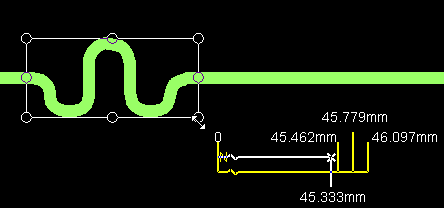
Once a pattern is added, you can edit it as a pattern when the box around it is visible as shown here.

At this point you can either stretch the pattern (using the handles) or move it by dragging your cursor on the box outline. This kind of editing will obey all the settings for Gloss as well as Push & Shove in from the Editor Control dialog. If you don’t want other traces affected by your editing, turn off “Trace shove” in the Push & Shove section.
There are two modifiers available when editing tuning patterns. These options are shown in the text field when editing a tuning pattern.
![]()
Editing Individual Segments:
You can also edit the individual parts of the tuning pattern, but first you must flatten the pattern. It can be flattened either by using the RMB menu or by holding down the Ctrl key when dragging on a trace segment.
Changing to Arcs:
If you have a pattern that was originally added with chamfers and you want to change it to a pattern with arcs, you need to change the Tuning dialog to turn on arcs, delete the original pattern and then re-add it. Another method would be to use the Modify Corners dialog, but that will flatten the pattern first.
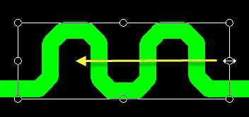
Deleting a Tuning Pattern:
Select one of the handles and drag it as shown in the image below until the pattern disappears.
Conclusion
What methods do you like for adjusting the length of the traces? Did I leave anything out? I believe what is important is to discover the methods that get your desired results as quickly as possible. We continue to enhance our tuning capabilities and would like to hear your feedback.


Comments