PCB Routing Solutions: Simplifying the Tuning Process – Part 1
What comes to mind when you are ready to tune the routing on a design? Among many thoughts, I seriously doubt that exclamations of joy are running through your head. Sure, after completing the routing of a circuit there is some excitement that a new phase of the process is starting; yet it doesn’t take too long for the fun coupons to run out as you have to deal with the tuning complexity and lack of space.
Resolving the timing requirements of a circuit by adjusting routing lengths can be accomplished in many ways, some more productive than others. Most designs will have length rules defined ahead of time, often provided by engineering; however, there are still some designers who will tune without rules and then add the rules just for checking. Many designers will manually add the tuning patterns one by one while using tools like the Tuning Meter to ensure that the task is done according to the rules. Others will setup the automatic Tune function to do as much as possible and then complete the process manually.
Regardless of the methodology, tuning is clearly an opportunity for the application of effective software to increase productivity. The multiple-part series will reveal the significant enhancements made in Xpedition Layout to simplify the process of tuning and enable results that are not only comparable in quality to manual tuning, but also enable the task to be completed much faster.
This first part is a fairly high level view of the tuning process. Additional parts will go into more details. When a design has numerous tuning requirements, not only can the act of adding length to the traces be a challenge, it is also sometimes difficult to understand when the tuning rules are fulfilled. I will focus on the Target Lengths dialog as a means to understanding the current state of tuning.
Target Length Dialog:
The Target Lengths dialog existed in 7.9.x; however, from the feedback I have gotten as I visit AEs and customers around the world, it is not well known. Rather than spending time discussing why it has not been used very much in previous releases, I will use this blog to describe the significant enhancements and its usefulness in the context of the Xpedition release.
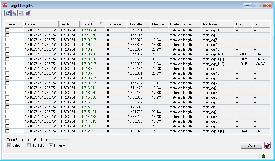
The Target Lengths dialog provides a view of the selected cluster that needs to be tuned. What is a “cluster”? When length or delay rules are setup (Min/Max, Matched Sets, or Formulas), the software automatically figures out the inter-relationships between all the rules and creates a set of From-Tos that are related to each other – this is called a “cluster.” This view of the cluster will tell you many things, but most importantly, it tells you which pin-pairs are tuned properly and which ones still need adjustment.
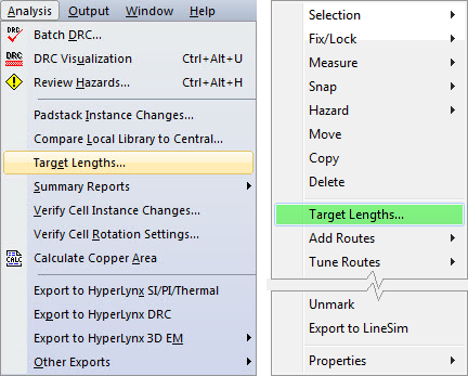
This dialog is launched from two locations: The menu pulldown and the RMB pop-menu (when a trace is selected).
In this case, I selected one routed net in the set of data lines for a DDR3 circuit. The rule here is a matched length rule where all these routes need to be the same length with a tolerance of 25th.
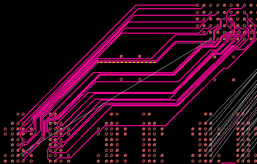
This dialog is context sensitive based on the cluster selected, when you select a net in graphics, the entire cluster appears in the dialog.

Overview:
- Target – The dialog will automatically select a Target; however, if you desire, you can select a target by checking the check-box.
- Range & Solution – The dialog has defined a Range and a Solution for each From-To. These values are not static and will likely change in order to find the most From-Tos with a Deviation of “0”.
- Current – This is the current length of the route. You may want to start with the longest ones and see if you can shorten them. This is because generally the longest one is chosen as the automatic target (although it may change as you make edits). By shortening the longest ones, you would make it so less tuning is required on the shortest ones.
- Note that one of the From-Tos is “Open.” The automatic Tune function will only work if all the From-Tos are routed in the cluster.
- Deviation – This is the most important column when starting the tuning process. This column is dynamic so any editing of the routes in graphics will automatically update the values in this column. If you decide to manually tune each item, you would modify the length until the Deviation is “0”.
- The Tuning Meter (turned on in the Display Control dialog) will give you graphical feedback on how close to the length of the route is to being within the Range.
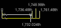
- The Tuning Meter (turned on in the Display Control dialog) will give you graphical feedback on how close to the length of the route is to being within the Range.
5. ![]() Refresh Solutions – The solution for each row is recalculated.
Refresh Solutions – The solution for each row is recalculated.
- Because solutions can be very complex if they are hierarchical or using formulas, it may be helpful to recalculate the solutions if some tuning is done and the rows are not updated as you might have expected.
6. ![]() Sync List with Graphic Net Selection – Double-click to toggle auto-sync.
Sync List with Graphic Net Selection – Double-click to toggle auto-sync.
- The list displays the cluster based on the graphic selection; however, if you select a net in graphics that is in a cluster that is different from the current cluster, you will get this message: “New cluster selected, press Sync List to update.”
- If you want to automatically change the list whenever selecting a different net in graphics, double-click the icon to auto-sync.
7. ![]() Sort Columns – Double-click to auto-sort.
Sort Columns – Double-click to auto-sort.
- The list is sorted on a particular column – in this example, on the Current column.
- You can resort the column by clicking on this icon. This saves you from having to click on the column header twice because the first time will reverse the sort order and the second click will resort it back to the original sort order.
- If you double-click the icon, the columns will automatically re-sort as changes are made.
8. ![]() Tune this cluster using tuning rules in Editor Control.
Tune this cluster using tuning rules in Editor Control.
- This performs the same function as F2 Tune.
- It will only work if none of the items in the cluster are “(Open).”
- There is a status bar at the bottom of the dialog that tells you it is still performing the Tune function.
9. ![]() Green = Cluster is tuned; Red = Cluster is not tuned.
Green = Cluster is tuned; Red = Cluster is not tuned.
Recommended Process (High Level):
- Consider shortening the longest routes in order to minimize the length to be added to the shortest routes.
- Setup the Tune dialog with the desired values and settings then use the Tune function. Once it completes, manually adjust the routes until all the Deviations are “0”.
- In another part of this blog, I will spend some time specifically on the Tune settings.
- If you prefer to use the manual methods for tuning, keep the Target Lengths dialog open so you can see which From-Tos have a deviation and need adjustment.
- Also, the manual methods will be examined in a later blog.
When Tuning is Complete:
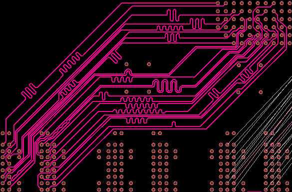
In this example, the Tune routine was used and you can see the results including the phase matching of the diff pairs.
Once the set is tuned, the Target Lengths dialog looks like this:
At this point with no deviations, and the green status light in the lower left, it is clear that this cluster is tuned.
Conclusion:
There are other methods of determining the status of tuning (like the Hazards dialog and using CES actuals); however, the Target Lengths dialog presents a very clear status of the tuning required. The future topics on this blog will explore additional details concerning successful and productive tuning. Whether you are adding the tuning patterns manually or automatically, keeping the Target Lengths dialog open during the process will enable you to dynamically see the results of your work and quickly determine the status of the cluster.
What to read next:


Comments
Leave a Reply
You must be logged in to post a comment.
Hello, charles.
It’s will be very useful to me. I expect the next topic.
VX target lenth is quite different than Expedition x.