PCB and Routing Solutions: Spreading and Centering Traces
This is the third post in this routing series. View the first and second post.
Board fabricators will tell everyone that spacing is king. If the traces can be spread apart and centered between via and/or pin pads, then it will result in higher yields during the fabrication process. Fewer shorts will be created and less work will be required to remove them.
In Expedition PCB and Xpedition PCB Layout, we have a “Spread” routine in the “Auto Route” dialog that will automatically spread the traces apart and center them between pads. Based on my discussions with many AEs and customers, I suspect that many have tried to simply run it from the “Auto Route” dialog and found that it did not work as expected.
In fact, the expectation was that it would only spread the traces. Centering them turns out to be an unexpected yet wonderful bonus. The reason why it doesn’t work as expected is due to the fact that it requires some very specific setup. First, a text side-file is required that has the appropriate spacing values per layer; and second, a check-box in the “Auto Route” dialog needs to be set. Let’s begin with the text side-file.
SpreadTo.txt
This file needs to be created and placed in the “Config” directory for the design you are working on.

The contents of this text file include the units, the layer and the corresponding spread clearance for that layer.
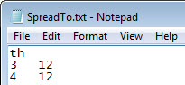
Units are “th.” By default, the units are the design units; so in most cases, this line is not even needed.
Then list the layers to be spread and the trace-to-trace clearance desired. Here, on both layers 3 and 4, the trace-to-trace spread clearance is 12th.
Auto Route Dialog
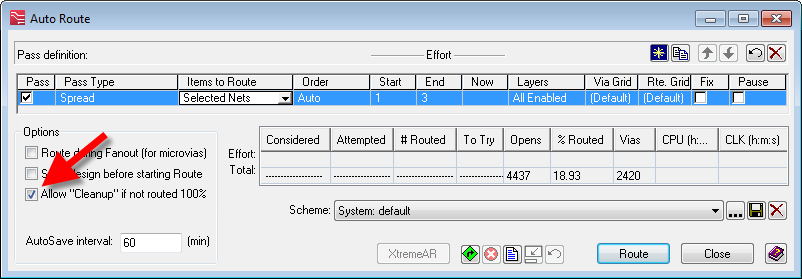
To enable “Spread” to work, the ‘Allow “Cleanup” if not routed 100%’ check-box needs to be checked. This is because when “Spread” is included with a number of other routing passes, it (along with other cleanup routines) should usually not be run unless the design is routed completely. If you are just using “Spread,” this check-box must be checked.
Run the “Spread” pass with a 1-3 effort. It will spread the traces as much as possible up to the spread clearance specified in the “SpreadTo.txt” file.
Example
Routing before “Spread”

After “Spread”

Note that the differential pairs are not spread apart, but they are also spread away from other nets.
Caveat: “Spread” does not push traces over via or pin pads. Because of this, you may want to move some traces around (as I did in this example) before running “Spread.” This will maximize the effect of spreading and prevent extra jogs in traces that are trapped between vias in open space.
Centering Traces
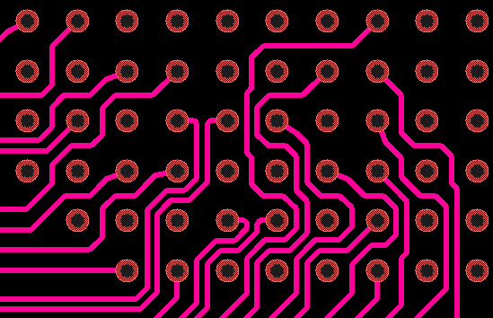
If the spread value is large enough, then it will also center traces between vias and pin pads. What is considered large enough? For example, if a trace will be centered between via pads with a trace-to-via clearance value of 8th, then any spread value equal to or larger than 8th will center the traces. You don’t have to get the value exact; in fact, usually it will be larger due to the desire to spread the traces themselves significantly – so that will work just fine!
Example
Before “Spread”
The white arrows point to some places where the clearance is at minimum spacing and it would be good to center or move the traces away from the pads.

After “Spread”
The traces are centered where necessary and move away as appropriate. Note that it will center just one trace or even two if needed.
Conclusion
In the previous discussion, it was all about a method for centering traces. Here we provide another method for spreading traces that also centers traces. Which method do you like better?