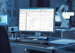
Siemens Capital software how to YouTube series: How to import 3D harness topology into Capital

Check out Siemens Capital software how to series and learn how to seamlessly import 3D harness topology into Siemens Capital. Efficiently integrate 3D data for enhanced electrical and wiring design workflows. Discover how Capital streamlines harness development, improves collaboration, and ensures accuracy from design to manufacturing.
As harness programs move toward manufacturing, it’s important to bridge the gap between mechanical design and production-ready documentation. Increasingly, harness topology originates in the 3D MCAD environment, but manufacturing and detailing workflows require an accurate 2D representation.
In this installment of the Siemens Capital How-To Series, we demonstrate how to import a 3D harness topology and transform it into a scalable, manufacturing-ready 2D layout.
The Challenge
In aerospace and other complex industries, harness topology is often defined within a 3D mechanical context. Connectors, bundles and protective coverings are positioned relative to surrounding structures, ensuring spatial accuracy within the vehicle or aircraft.
However, manufacturing documentation and form board preparation require a clear 2D layout. Converting 3D topology into a 2D drawing manually can be time-consuming and prone to distortion. Relative connector positioning must remain accurate, scaling correct, and the resulting layout aligned with company drawing standards – all difficult to accomplish using manual methods.
At the same time, designers need visibility into incoming topology before committing to processing it, to ensure the structure can be validated prior to flattening.
The challenge is to translate complex 3D harness data into a structured 2D representation, without losing design intent or introducing errors.
How to translate 3D harness data into a 2D presentation
With Siemens Capital, designers can import 3D MCAD harness topology directly into the design environment.
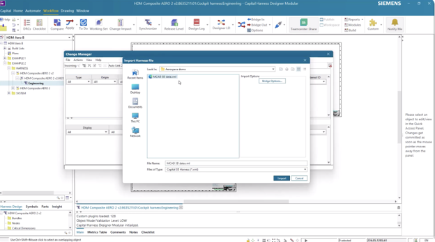
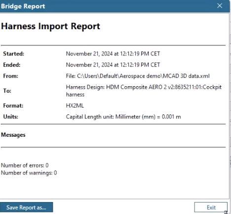
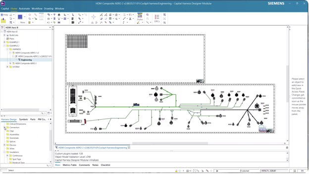
The system automatically flattens the 3D topology into a 2D layout while preserving the relative positions of connectors and structural elements.

Before processing, the designer can explore and review the incoming topology, gaining confidence in the source data.
Once the layout is flattened, the design can scale it appropriately and arrange it to meet documentation standards.
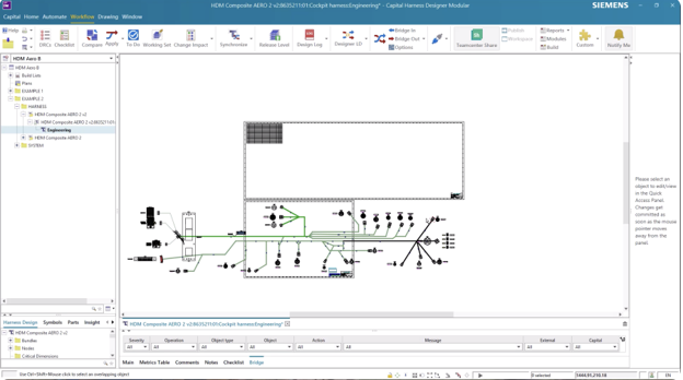
Next, the designer can select a standard drawing border from the library and rearrange elements as needed, to create an organized representation.

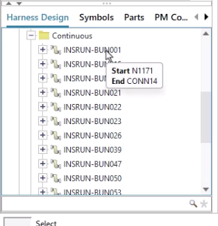
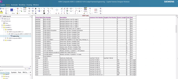
As the topology is processed, Capital generates a comprehensive harness Bill of Materials table automatically.
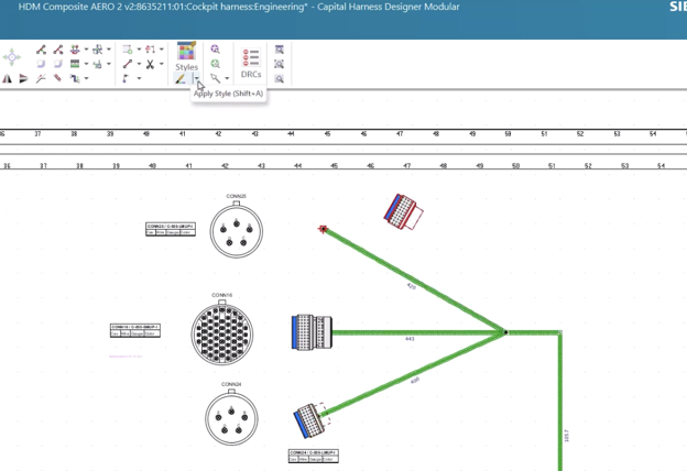
The designer can then customize the design object appearance and layout to align with internal standards and manufacturing requirements.
Within a streamlined workflow, 3D mechanical harness data becomes a structured 2D layout that’s ready for synchronization with electrical data and downstream manufacturing preparation.
Capital benefits
Siemens Capital accelerates the transition from mechanical topology to manufacturing documentation by automating 3D-to-2D flattening while preserving design accuracy. Benefits include:
- Connector positioning, bundle relationships and structural intent remain intact throughout the process.
- Automatic BOM generation ensures that documentation reflects the full harness definition without manual compilation.
- Flexible layout tools allow teams to align designs with company standards quickly and efficiently.
By connecting MCAD topology with harness design workflows in a unified environment, Capital reduces manual effort, shortens preparation time and strengthens confidence in manufacturing-ready data.
Read the full blog series to learn more ways Siemens Capital simplifies and streamlines harness design.
Capital X is the SaaS (Software-as-a-Service) version of the Capital portfolio that has been the leading solution for comprehensive E/E systems development for over two decades. Capital X, operated by Siemens, offering a comprehensive digital twin and seamless collaboration to optimize the design, engineering and validation of complex products. Click here to learn more about Capital X.