Building blocks for better wiring harness manufacturing engineering

The speed with which wire harness makers can bring new or changed designs successfully into production is a key competitive advantage in a historically low-margin industry. Many modern platforms, from automobiles to airplanes to robots, rely on electrical/electronic content. Subsequently, the wire harnesses that inter-connect devices have become critical components on the platform delivery path.
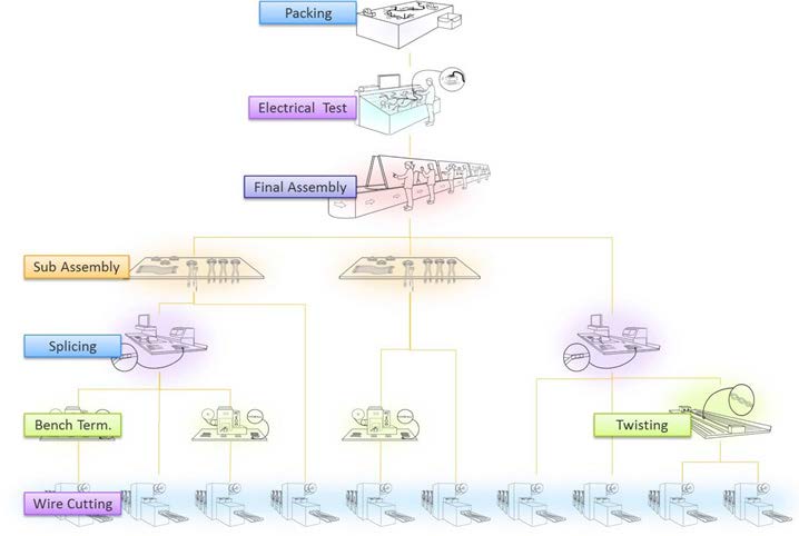
Despite this business imperative, harness manufacturing engineering – the complex series of tasks that occur before new product introduction (NPI) – has been poorly served by commercial off the shelf (COTS) software. Complicated wire harnesses are not built in a single step. They are built by a sequence of operations such as those outlined in Figure 1. While some operations can be automated, many are still manual. More importantly, the exact details of each step will depend on the harness design. It will also depend on build volume, and the product facility’s capabilities. As a result, wire harness makers have been forced to write their own in-house applications or depend on semi-manual methods.

Fortunately, more and more COTS software solutions now incorporate four technology “building blocks”. These improve wire harness manufacturing efficiency and streamline the time it takes to go from design to NPI. Let’s examine each one in more detail.
Building Block #1: Capturing harness design data
The first building block is a rich digital description of the harness to be manufactured. The idea is to “build to data” as opposed to “build to print”. It’s impossible to support efficient NPI by launching the process from an unintelligent harness drawing. While formatted drawings convey a lot of information and are often a contractual artefact, engineers need a solid data foundation to implement automation. This building block ensures the COTS tool provides engineers with digital data to visualize the modeling of the harness design along with functionality such as design rule checking (DRC) and configurable reporting.
Building block #2: Manufacturing process synthesis
The second building block is the ability to automatically synthesize the detailed harness manufacturing process tree. This is sometimes known as the structured bill of process (SBOP). The SBOP depends on the specific harness design. It includes each configuration variant, as well as on production capabilities, such as whether a machine can strip and terminate both ends of a wire. Harness manufacturers often have several factories in which they can build any particular harness, or at least a choice of production lines. This means that production capability models must be detailed, specific, and re-usable. This building block allows the COTS tool to offer a rules-based process synthesis engine that specifically addresses harness manufacturing.
Building block #3: Advanced graphics generation
Building block number three combines design data with graphical rules to automatically render the correct visual outputs. It’s comparable to the way a process synthesis engine combines design data with process models to create SBOPs. The goal is to eliminate tedious, error-prone redrawing by creating harness drawings automatically styled for different purposes directly from the underlying harness design data. One use case for advanced graphics generation is formboard design. Full-scale formboard diagrams are generated directly from the engineering environment. The formboard is the graphic representation of the data — not the result of a drawing. This building block enables the COTS software to render full-scale drawings, change symbols, and adjust branch layout.
Building block #4: Digital continuity
The fourth building block is digital continuity, which provides a seamless data flow in order to avoid data re-entry costs, errors, and delays. Within a well-designed single software environment this is fairly straightforward. But it’s more challenging when data must transition between environments. For example, wire length data from harness design to cutting equipment or sub-assembly patterns from process tree calculation to ERP. Digital continuity also enables easier data navigation. For example, sometimes an engineer wants to understand why expensive gold-plated terminals have been specified (or automatically selected) for some wires. This COTS software building block ensures that the engineer can navigate backwards to the logical or even functional source of the signals implemented by those wires.
Taken together, these four technology building blocks underpin an exciting new generation of COTS software solutions. The Siemens Capital® product suite can help you achieve your construction goals. By reducing manufacturing engineering costs and improving process quality, these solutions are transforming manufacturing engineering NPI from a costly in-house application to a highly automated competitive advantage. To learn more, check out A robust solution for wire harness engineering.


