Designcenter NX | How To | CFD Designer

In our latest Designcenter™ NX™ software How To video, we explore how Designcenter NX CFD Designer empowers you to rapidly set up, run, and compare computational fluid dynamics (CFD) simulations directly within your design environment. This set of commands makes it incredibly easy to go from raw geometry to meaningful thermal and flow analysis results, dramatically speeding up your productivity for applications like early-stage cooling analysis and fan selection for motor assemblies.
Check out the video below or scroll down to learn more about how to leverage Designcenter NX CFD Designer to perform fast, flexible flow simulations and make informed, data-driven design decisions earlier in your development process.
What is Designcenter NX CFD Designer?
Designcenter NX CFD Designer is an integrated solution within the Designcenter NX environment that allows engineers to perform quick and accurate computational fluid dynamics (CFD) simulations. It’s designed to streamline the analysis process, enabling users to validate designs early in the development cycle without needing to export geometry to separate analysis tools. This seamless integration means less time spent on data transfer and more time focused on design optimization.
Key benefits of CFD Designer include:
- Integrated Workflow: Conduct simulations directly within the familiar NX interface.
- Rapid Analysis: Quickly set up, run, and compare thermal and flow simulations.
- Early Design Validation: Make data-driven decisions sooner to reduce development risks.
- User-Friendly Interface: Intuitive, workflow-driven layout guides you through each step.
- Enhanced Productivity: Features like batch runs and project cloning save significant time.
An Intuitive, Workflow-Driven Interface
Designcenter NX CFD Designer is built around a logical, left-to-right interface layout that naturally guides you through each stage of your simulation workflow. Rather than jumping between disconnected tools, every function you need from geometry preparation to results visualization is organized in the order you will actually use it, keeping your process clean and efficient.

Geometry Checking and Preparation
Before any simulation can begin, CFD Designer includes a built-in geometry check tool that identifies any parts or features that may cause issues during analysis. Errors are clearly flagged, and the Display option adds text tags directly to the geometry so problem areas are easy to locate and resolve.

Beyond geometry checking, CFD Designer also provides tools to help simplify and prepare your model for simulation. The Create Lids function is particularly useful for both internal and external flow simulations, simply select a face on an open surface and CFD Designer will automatically generate lids for every opening, quickly creating the enclosed volumes needed for accurate flow analysis.

Streamlined Project Setup with the Wizard
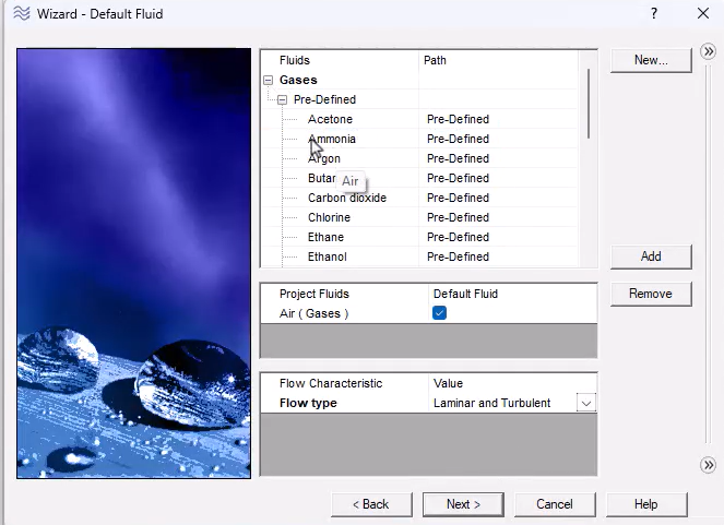
Once your geometry is ready, the Setup Wizard guides you through every aspect of your project configuration in a clear, step-by-step sequence. You can start by naming your project and configurations, keeping multiple design studies organized with meaningful names. From there, you select your preferred unit system, choosing from an existing set or defining a custom one to match your workflow. Next, you specify your analysis type, selecting between external or internal flow simulations depending on your application, followed by fluid selection from a broad library of gases and liquids where you can also define your flow characteristics. Solid materials are then assigned to components, with the flexibility to add custom materials directly from the Wizard. Finally, wall roughness and other custom parameters can be fine-tuned to match your specific design requirements.
Once all settings are configured, selecting Finish automatically establishes the foundational structure of your project, ready for boundary condition setup and further refinement.
Defining Boundary Conditions and Simulation Inputs
With the project set up, the CFD Designer Navigator provides a centralized view of all your input data, making it easy to review and modify settings at any stage. From here, you can define and adjust inlet and outlet boundary conditions, including volume flow rates, pressure conditions, and flow directions. Solid material assignments can also be set or updated for any component in the assembly. Additionally, volume and surface sources allow you to define heat generation across individual components or distributed across total volumes, giving you precise control over how energy inputs are represented in the simulation.

Setting Simulation Goals
CFD Designer allows you to define simulation goals, specific parameters you want the solver to track and report on throughout the analysis. With a wide range of available parameters to choose from, you can focus the solver on exactly the outputs that matter most to your design evaluation, such as surface temperatures, flow rates, or pressure values, making it straightforward to assess whether your design is meeting its performance targets.

Cloning Projects and Running Batch Runs
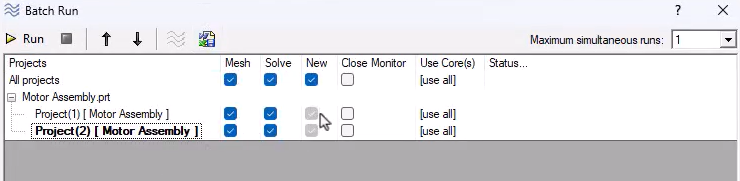
One of the standout productivity features of CFD Designer is the ability to clone an existing project and modify specific parameters such as flow rates or material assignments to quickly generate alternative design configurations for comparison. Once multiple configurations are ready, the Batch Run feature allows you to solve them all simultaneously in a single run.
As the batch solve progresses, you can monitor convergence in real time by extracting goal plots while the solver is still running, giving you early insight into results without having to wait for the full solve to complete.
Visualizing and Comparing Results
CFD Designer provides a powerful suite of visualization and comparison tools to help you extract meaningful insights from your simulation results. Cut plots and surface plots allow you to visualize temperature distributions, flow patterns, and other key parameters across your assembly. Compare functions let you display results from multiple projects side by side to directly evaluate the performance differences between design alternatives. Finally, difference plots generate a visual representation of the quantitative delta between two solutions, making it easy to see exactly how one design configuration outperforms another.
Pro Tip for Viewing Results: To get a clearer view of your simulation outputs, especially for internal flows or complex assemblies, you can easily hide model geometry. This allows you to focus purely on the thermal and flow patterns without visual obstruction.

Summary of Designcenter NX CFD Designer
CFD Designer in Designcenter NX gives engineers a fast, accessible path from geometry to actionable simulation results, all without leaving the familiar NX environment. By combining intuitive project setup, flexible boundary condition configuration, powerful batch solving, and robust results comparison tools, CFD Designer enables meaningful early-stage design validation that helps you make smarter design decisions sooner, reduce development risk, and bring better products to market faster.
Continue your journey with Designcenter NX
Watch the Designcenter NX Synchronous Modeling Tips and Tricks Video here ▶️
Watch the Designcenter NX Structure Designer Tips and Tricks Video here ▶️
Take me to the NX design blog 📚