How do you track changes made to your CAM files?

PCB DFM comparison of CAM files
CAM Compare is a popular DFM tool that comes packaged with every version of Valor NPI which sees widespread use within most iterative PCB design workflows. It allows any two CAM files produced from virtually any CAD tool to be examined side-by-side to explore any changes present between the two files. It is the de facto version control tool for ODB++ and is an indispensable way to track changes made by multiple individuals, within multiple organizations, and across multiple file types.
CAM Compare has seen significant updates with the 11.5 release, expanding its capabilities to intelligently compare fabricator data to original design data and to present typical fabricator changes in a straight-forward manner. CAM Compare provides a detailed list of physical differences within any two CAM files. Supporting ODB++, IPC2581, Gerber 274X, IPC-D-356A, Excellon drill data or other EDA flow data.
CAM Compare can be used between similar data sets to do a detailed revision control, or between two different datasets to ensure that an accurate conversion took place. It can be run on the entire design, or just upon a specified area within the larger design. As the calculations are performed on a raster graphic comparison, a tolerance value can be set to control the size of the raster grid used for the comparison, allowing the user to control the granularity of the comparison, effectively ignoring differences below a threshold resolution.
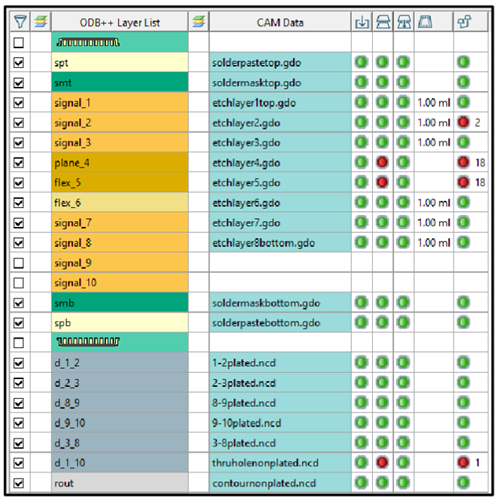
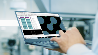
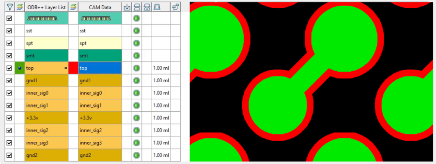
Cam Compare shows the layers with differences between the two datasets by highlighting them in red.
PCB Copper Etch Compensation
In the most recent release of Valor NPI, CAM Compare has been given the functionality to read and accommodate for etch compensation performed by the fabricator. Depending upon the copper weight used, fabricators will typically thicken traces by regular amounts, ensuring that when the etch is complete, the traces have been cut to their desired width, and the etch undercut has not shrunk the trace to unacceptable widths. CAM Compare’s new functionality, “calculate resize” is able to read this etch compensation and accommodate for it during DFM review, thus eliminating many unnecessary false errors during CAM Compare.
A similar methodology has been put in place for any drill resize changes necessary from the fabricator. The compensation can be measured and accommodated for to reduce false errors, and another option for drill comparison is allowing a user to compare on drill position only.
Once the etch compensation value is calculated, this tolerance can be accepted during DFM review, or the value can be adjusted further based on the needs of the designer. This allows you to review and accept or reject these changes as a whole, or in part.
PCB CAM files from a CAD tool
In most cases, CAM Compare is able to perform most of the stages required to fully examine and compare two data files. It can read and match reference data, identify matching layers, coordinate registering layers, and compare the result. There are however instances where layout and naming may have changed between revisions. In these cases, it is possible to perform layer matching individually between available revisions. Explore the use cases for CAM Compare within our short video, or take a test drive today within our Valor NPI free trial.