Modeling Kinematic Devices in Simcenter Motion for use in Process Simulate Kinematics
This article was authored by Hans Kopp
(please scroll to the bottom of the article for instructions on using the Process Simulate on Teamcenter Solve NX Kinematics command)
Guidelines and best practices
For this purpose, a kinematic device in Simcenter Motion must follow some rules, because Process Simulate can handle only a subset of the kinematic devices that you can create in Motion.
Note: “Simcenter Motion” is the motion application name, starting NX11. In older versions, the name is “NX Motion Simulation”.
Supported types of simulations (Motion dialog box Environment)
When you create a new simulation:

- Analysis Type must be Kinematics.
- Component-based Simulation check box must be selected.

Process Simulate supports only a single kinematic definition per component.
Mechanism definition requirements
There are no restrictions on the creation of links. Because the simulation is component-based, you can use only assembly components as link geometry.
- If an assembly component has its own kinematic definition, you can still use it as a link geometry of a parent kinematic.
- You cannot use the child components of the component in the parent component.
- Joints must be Revolute or Slider joints. Both types of joints must have both the Action Link and the Base Link defined. For Process Simulate, it does not matter which link is action and which is base.
- The names of the joints must be alphanumeric, with the first character only alphabetical. Other characters are not supported by Process Simulate and will be replaced by the kinematic solver.
- There must be one Fixed type of joint that connects one of the links to ground. This joint should define only the action link but no base link. The link that is marked this way will become the root link in Process Simulate – that is, the link that is fixed to ground.


Note: You can also connect a link to ground using a Revolute or Slider joint, but this is not the recommended workflow.
In general, the kinematic graph must be tree-like. The allowed exceptions to this – the cranks, are listed in section 4 below.
Exporting kinematic model to Process Simulate
- In the Simcenter Motion Navigator, select the Simulation node and select Export/Process Simulate Kinematics. You must repeat this step for each device that you want to export. This creates a data set of type kinematics on the item revision of the device in Teamcenter.
- You must export the JT files for all the sub components of the device.
To load the device in Process Simulate, assign the item revision of the device to a process and open this process in Process Simulate. For tree-like kinematics, no further steps are needed; the kinematics will be immediately usable (for example, in the joint jog).
The joint limits of the joints will be transferred.

Exporting cranks
Process Simulate supports the import of the most frequently used crank types.
When creating a kinematics with cranks in Simcenter Motion, you must verify that the crank types are supported by Process Simulate (see Supported types of cranks below). Otherwise, it will not be possible to move the kinematics in Process Simulate.
In addition, you must define the driving joint for each crank to be exported. The driving joint is the joint that should be jogged in Process Simulate. The other joints of the crank will be dependent on the driving joint.
To define the driving joint in Simcenter Motion, create a joint Driver for a single joint of the crank. The type of driver and the parameters of the driver are not used by Process Simulate.

Note: The export of the driver is available only since NX11. If the kinematic should be created with NX 9 or NX 10 then Process Simulate will use that joint as driving joint the joint name of which comes first in the alphabet. Upper case letters are considered to be before lower case letters here. Thus if there are e.g. the joints with names ‘a1’, ‘C1’, ‘b1’, ‘D1’ in a crankthen the joint C1 will be used as driving joint. If a wrong driving joint is selected the crank might not be solvable as the crank type is not supported.
Apart from the information listed above, the creation and the export in Simcenter Motion is the same as for tree-like kinematics.
Importing cranks in Process Simulate
The import of a kinematics with cranks requires an additional manual step in the import to Process Simulate. After loading the kinematic device to Process Simulate, you must run a solve for the cranks.
To do this, customize the command Solve NX Kinematics in a ribbon, select the imported device, and run the command. The command (described in detail below) will analyze the kinematic and solve all cranks of the kinematic. If the kinematic cannot be solved, an error message is displayed.
When solving the kinematic, the kinematic graph is transformed into a tree. You cannot export this transformed tree back to Simcenter Motion.
Supported types of cranks
The following crank types are supported by the kinematic solver in Process Simulate. Both the driving joint and the fixed link must correspond to one of the pictures below. In each picture, the arrow indicates the driving joint and the dashed link represents the fixed link.
RRRR

This is a crank with four rotational joints, all of which have the same joint direction. The driving joint is connected to the fixed link.
RPRR

This is a crank with a single prismatic joint and three rotational joints. The prismatic joint is the driving joint. The fixed link is not connected to the prismatic joint.
PRRR

This is a crank with a single prismatic joint and three rotational joints. The prismatic joint is the driving joint. The fixed link is connected to the prismatic joint.
RRRP

This is a crank with a single prismatic joint and three rotational joints. A rotational joint is the driving joint. The fixed link is connected to both the prismatic joint and the driving joint.
Compound cranks
You can combine the crank types above into compound cranks. With compound cranks, you can create kinematic structures with two or more kinematic cycles that share a single joint and two links. Only one crank of a compound crank can have a driving joint. For the other cranks, the shared joint will become the driving joint.
Here an example of a combined RPRR and RRRR crank – a three-point crank.

A kinematics can have multiple cranks that do not share a common joint, but share only a link or do not share any elements.
The Solve NX Kinematics command in Process Simulate on Teamcenter:
You can import the kinematics of an equipment from NX Motion to Process Simulate on Teamcenter. First it is necessary to export the assembly’s NX Motion kinematics and JT files to Teamcenter and them import them with Process Simulate.
After loading to Process Simulate, the application automatically reads this equipment – if the kinematics did not contain any cranks (kinematic cycles), the device can be used right away.
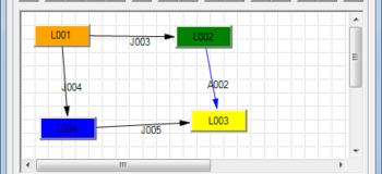
If it does contain cranks, you can try and solve the device by selecting the node and using the Solve NX Kinematics ![]() command. This is necessary in order to enable using Joint Jog and other commands for the device. To see if a device contains cranks, you can open the Kinematics Editor for it – cycles in the graph indicate that you need to solve the kinematics:
command. This is necessary in order to enable using Joint Jog and other commands for the device. To see if a device contains cranks, you can open the Kinematics Editor for it – cycles in the graph indicate that you need to solve the kinematics:
Notes:
- Make sure that devices are not in modeling mode when using the Solve NX Kinematics command.
- After fixing the device’s kinematics in the Kinematics Editor, use the End Modeling command and then perform Teamcenter Update.
- The command supports multi-selection or selecting a compound node to solve all devices under it. An informative message displays in the event that the command did not solve the device or If problems occurred.
- You can customize the command as needed.


Comments