Working with Units and Standards in Solid Edge
For those of you outside of the US, Monday was Labor Day, which kind of demarks the end of summer. So my usual Monday-Wednesday-Friday schedule has been disrupted a little. I’ll be back on track next week.
Don’t let all that power go to your head
Solid Edge offers users a lot of control over how it deals with units and drafting standards. The philosophy that Edge uses is that the drawing should always look the same, regardless of where it is opened or who opens it. This is a great philosophy and I understand why it is so appealing to most Solid Edge users.
Not all software works from the same assumption, however. Solid Edge is largely about control and consistency, especially in drawings. Other CAD software may be primarily about ease of use. Ease of use does look good on the surface, but once you get into it, you realize that the software is making some automatic decisions for you, and these may not always be the best choices for you and your way of producing parts, assemblies, and drawings. For example, in SolidWorks, you can take a drawing from one computer, open it on a different computer, and something like the system delimiter might change (some areas use commas instead of periods to delimit the 1s place from the first decimal place, so 25.4 vs 25,4).
Solid Edge offers several places to control the display of dimensions using units, delimiters and standards. This article is mainly about identifying the different controls, and explaining what they do.

Templates and Standards
Templates are used to specify which dimensioning standard (ANSI, ISO, etc.) and unit (inch, mm, etc) is used for a new document, along with a lof of other settings. You can’t switch templates for existing documents, but you can switch all the settings used to create the template in the first place.You can create a template from any document, and templates just have the same extension as the type of document they are used to create. So, for example, a part template will have a *.PAR extension, and a draft template will have a *.DFT extension.
If you want to have a special location for your templates, you can use the File Locations settings to help you tell Solid Edge where that location is. You can find the setting at Application Menu > Solid Edge Options > File Locations > User Templates.
The default templates can be set in Application Menu > Solid Edge Options > Helpers > Set Default Templates.
ISO vs ANSI and Projections
Please be aware that ISO and ANSI standards are not interchangeable. If you’re in the US and are producing ISO drawings, you need to make sure that you are aware of the difference between first and third angle projections. Most folks in the US are accustomed to reading third angle, and you can get incorrect parts if you send the wrong projections on drawings. Because Siemens is a highly international company, you may find Solid Edge documentation created using Standards that you are not familiar with. When you install Solid Edge, you get the choice of selecting ISO or ANSI, and I would not treat this as a trivial decision. You should make sure you understand the requirements of your company and your customers to make sure you get the right one. With any new installation, I recommend that you do a test drawing to make sure that you’ve got the right projection style. To learn more about first vs third projection, read here.

In a drawing document, you can control some of the standards settings including first or third angle projection at Application Menu > Solid Edge Options > Drawing Standards.
 Units
Units
If you have an empty document where the primary unit is millimeter, and you want to change it to inch, you have to do a couple of things to make the change complete. First, go to Application Menu > Properties > File Properties > Units, and set that to the units you want to use.
Next, go to Application Menu > Solid Edge Options > Dimension Style, then make sure the Use Dimension Style Mapping option is checked. Then under Set All Styles, select the option you want, for example ANSI (inch), and click the Apply button right next to the setting. Then click the Apply button at the bottom of the dialog.

If you have a part document that already has some PMI dimensions applied in it, the above steps will not change the existing dimensions. To change these, you have to select all the dimensions you want to change from the Pathfinder PMI collector, shown below, then in the Command Bar, under Format, select the standard and unit type that you want to change the dimensions to. You can also select the dimensions from the graphics area, but make sure that when you do, you select the dimension arrow, not the dimension value. This Format setting can also be accessed from the View tab, in the Style group, from the icon called Styles.

Remember that typically when you change units, you may also have to change the number of decimal places (called Round-Off in Solid edge).
The ability to select PMI dimensions from the Pathfinder is another one of those really nice gems in Solid Edge. In addition to selection, you can also hide/show and lock/unlock dimensions in the Pathfinder. Works doesn’t have a comparable capability.
Just as a caution, you can easily get yourself into a situation where the dimension on the screen reads in one unit, and the dimension in the modify dialog reads in another. If this happens, remember, that this last step is meant to change the existing dimensions.
 Delimiter
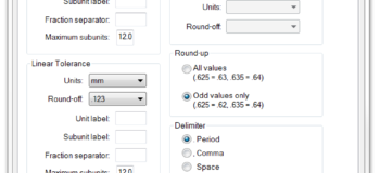
First, what is a delimiter? The delimiter is what you use to show where whole numbers stop and decimals begin. The conversion from inch to cm is 2.54 with a period delimiter, or 2,54 with a comma delimiter. The comma delimiter may come automatically with an ISO standard template. Windows typically sets a system delimiter, but Solid Edge uses its own.
Why is this a big deal to me? Because I once saw someone with a document on screen that had mixed delimiters. I just thought it was odd. I’ve never run across a situation where I was asked to do this kind of thing. In order to access the delimiter settings on a per-dimension basis, just right click on the dim and select Properties, then go to Units.
This dimension properties dialog is huge and allows you to control a lot of things about the display of dimensions in Solid Edge. It’s now no wonder to me that Solid Edge has had such a superior reputation when it comes to drawings.
Summary
The controls for units and dimension display are complex and powerful in Solid Edge. It is worthwhile to take some time to familiarize yourself with what each of these does. Even if you never need to set the settings yourself, you may need to undo something someone else has done. It’s great to have control over software. Often times ease of use comes at the expense of control and flexibility.


