What is Your Modeling Style ?

That the purpose of 3D modeling and drafting is ultimately to convey the design idea for downstream analysis and/or manufacturing is a no-brainer. This is year 2017 and stating that the ability to create digital prototypes of objects before they are manufactured is a boon sounds too retro. With advancements in solid modeling and hundreds of enhancements pouring in with each release of Solid Edge, the big question still is – do we really follow a modeling style, a modeling workflow or a modeling strategy that actually mimics a manufacturing process that the raw material undergoes through the final product?

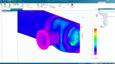
Look at this shaft which represents the final design. Does it reveal how it was modeled. One way of modeling this shaft would be by revolving a sketch. Does that match your style? Another way which you were perhaps compelled to follow was to extrude smaller cylinders end to end because the information was provided in terms of the various diameters and lengths ? or did you, using the same information chipped off the waste portion from raw cylindrical stock ?
Your design intent would largely govern the method you adopt. In the heydays of ordered modeling, sketching 2D elements was followed by building features on top of them. This workflow essentially locked your design intent. Once the shaft was modeled using a particular method, the design was tied to the sketches and so was your design intent. There was no way you could easily go back and think of modifying the design in an alternative way.
The model appeared adamant or resistive to edits because the underlying sketch has hijacked your design intent. Modifications to the model were no longer possible outside the limits of what the sketches would allow.
Synchronous Technology bestows designers with enormous design freedom. You still start with 2D objects which actually create 3D regions with zero thickness that can be extruded or revolved or lofted or swept as per the form and function. This still appears traditional and you can proceed with any of the aforementioned techniques to create the 3D model. What follows next is a huge differentiating factor – you can simply forget the sketches – forever! In fact in the Synchronous environment, sketches themselves exhibit gracefulness and line up under the Used Sketches collector so they no longer come in way of editing the model or the design intent. You can delete those with no harm to the model but it is best to leave them in the Pathfinder.
Subsequent to this, faces can be freely pushed or pulled or rotated. Occasionally you can decide to delete some. Sketches will not hinder your ability to manipulate the model geometry. You are in direct charge of your model and your design intent. Plunder the wealth of features that the Solid Edge synchronous environment wholeheartedly offers like the Steering Wheel, using formulas for model dimensions, 3D face relations and so forth.
Yet some designs lend themselves to be modified best at the cross-section level. The shaft in case is a good example. You are not at a loss when the sketches are long gone, because the Synchronous environment provides another gem of a feature called the Live Section that can be placed directly on a model. Sections in 3D models are not new and Solid Edge has had this facility for a long time. What sets apart a Live Section from its previous avatars is that they are live, as the name suggests. Changes made to a Live Section influences the model geometry.

A Live Section can be created quickly by simply picking a nearby face or reference plane and then moving it freely to the desired location using its Steering Wheel. Apply just those dimensions to the Live Section elements that matter to your currently intended modification. This is unlike a sketch-driven feature which ideally calls for a fully constrained underlying sketch for guaranteeing a failure-proof future. This comes built-in with synchronous models since the model is not obliged to come equipped with all the know-how for a successfully rebuild of all features.
Unlike sketches, Live Sections can be multiple. You can create several of them even in imported geometry at places where you feel edits are to be made. The number is limited only by imagination and the intended changes in a 3D model.
Ultimately, Live Sections can be disposed off which means they can be simply deleted. This is because new ones can be created any time and at any location in the model. Unlike underlying sketches which need to be carried along with the 3D model as a burden, Live Sections are lightweight, in fact weightless and this in turn also reduces the model regeneration time.
Since there are no underlying sketches, no 2D relations to solve nor any overhead of fully constraining the sketch, it makes the design process faster and the models robust and lightweight all at the same time. Do you find this anything less than a miracle ?
With all virtues of Live Sections highlighted and underlined, the time to start using one is now. Nothing should stop you from sharing your models or just the images and seek advice upfront on how you could use Live Sections in your design if you are not sure. Experts on the Solid Edge forum would be more than willing to show you the way.
Also, if your company policy permits, share images of models showing how you have already used Live Sections in some of your designs in the comments section below. If not, then a short description about your intelligent use of Live Section too are a welcome.


Comments