Two Nice Bits of Drawing Automation
 This week I came across a couple of drawing automation bits that are really nice, and I just want to call attention to them for those who maybe never knew about them, or maybe those who have forgotten. These two bits are Callouts in the title block, and Quicksheet Templates. My research for this article was done completely within the on-line Help, and just playing with the software. Let’s talk about Quicksheets first.
A Quicksheet template is a drawing template with empty views on it, where the drawing views will be automatically populated when you drag a part onto the drawing from the Library or from Windows Explorer. You can make a Quicksheet template from an existing drawing using the command from the Application Menu shown to the right. When you do this, you’ll get the message below, reminding you that Solid Edge will remove the geometry from the views, and you won’t be able to undo this operation.

Some of the properties from the now empty views will be retained, and some will not. The ones that are kept are general view properties, text and color properties, and annotation properties.
If you created your Quicksheet template from an assembly drawing with a Parts List on it, you can repopulate the Parts List by just dragging a model onto it (presumably from the Library or Windows Explorer). Automatic ballooning will happen if it is an active property of the empty view.
When you save the Quicksheet template, remember that your default template location is C:Program FilesSolid Edge ST6Templates. Save it with some name so that you’ll know what the purpose of the template is.

The numbers under the views are just labels showing the scale of each view. The labels will disappear as soon as the views are populated. Notice that even the section and auxiliary views were saved and will be recreated.
Just for comparison, yes, SolidWorks has functionality called “predefined views”, but they are not this powerful nor are they as easy to create.
To use Quicksheet templates, just start with the New command, and select the Quicksheet template from the list, then drag and drop a part or assembly from the Library or Windows Explorer onto the sheet. Normally you would use the View Wizard to get started.
I think Quicksheets are a great time saver, especially if you make drawings with the same views on them frequently. How many of you out there use these? Leave me a comment with the types of views on your Quicksheets.
The next type of drawing automation functionality is the Callout tool, which can be placed on the drawing and configured to pull values from the model (part or assembly). The Glossary in Help says:
Callout: A type of annotation that consists of a text box with a leader.
Although I see a lot of these without leaders.
And then here’s the Help for the Callout Properties dialog box:

What’s the first thing you notice about this? The first thing I notice is that it doesn’t show the Callout Properties dialog box. Here’s the dialog box:

Yes, I know it’s difficult to translate such a busy dialog box into a dozen or more languages, but leaving it out means you’re not really communicating in any of the languages. I don’t mean to be harsh, I just don’t think you can talk about the interface without showing it.
The real 800 pound gorilla here, at least for me, as a relative noob looking at this, is “what do all those strings mean?” You can get the meanings for all the symbols as tool tips, but that’s not so helpful when you need to go the other direction (to read the callout strings). So here is a list of all the callout strings that I could find:
Symbols

Feature Reference (dimensions)

Callouts are often a combination of symbols and dimensions, so a typical counterbore hole callout would be coded this way:
%DI %HS %ZH%RT%CB %DI %BS and would look like this
 To place these, you use the Callout tool on the Home tab, Annotation group, copy the set of codes from the Feature Callout tab into the Callout Text box on the General tab (of the Callout Properties box), click OK, then select the edge of the hole where you want to place the callout.
This copying seems a little lame, it seems like I’m missing some step. With all of the feature recognition that goes on in Solid Edge, the software should be able to recognize what is selected, and be able to select which callout to use. I’m probably missing something here. Can someone straighten me out on this?
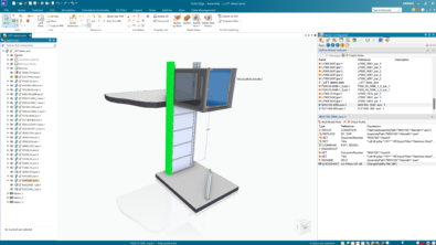
The Property Text is another automated annotation, and you can create it from inside the Callout Properties. Notice under the second row of icons there is an A symbol with a finger pointing to it.

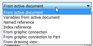
This is the Property Text icon, and will pull properties from another location to put into the callout/annotation. On the right of the image above, you can see a list of properties that can be pulled. These are the types of annotations that you see in the title block of the drawing that should be populated automatically from some other specified location, usually the part or assembly on the drawing document. The drop down list above that shows where the properties can come from:
- Active document
- Variables from active document
- Named reference
- Index reference
- Graphic connection
- Graphic connection to part
- Drawing view
It’s not clear to me how all of these work, but what I can tell from here is that these options completely blow away anything that Works offers.
The deeper I dig into this software, the more I’m blown away by the powerful capabilities in here. How have you all kept this stuff so quiet for all these years?