Synchronous AND Parametric
There is this misconception going around that synchronous models are somehow not parametric. You can have one or the other, but not both. I suppose that’s because a lot of people equate history-based modeling with the word “parametric”, and anything else must be different.
The truth is that synchronous parts are entirely parametric. We’re not messing with definitions, playing word games or exploiting some technicality when we say that. In every traditional sense of the word, “parametric”, synchronous parts fit the bill. The parts are driven by dimensions and geometrical relations, and the dimensions can be driven by either values or equations.
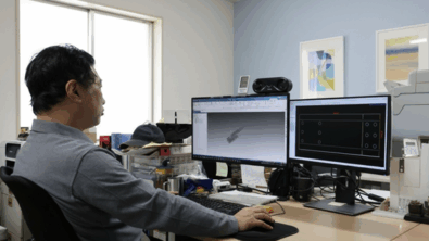
 Here’s a simple example. This part is synchronous, so it has features, but the features are essentially collections of faces, and it was created using sketches, but the sketches aren’t controling anything, they’re just there as legacy. The dimensions are attached directly to the 3D geometry, and the red ones are driving, the purple ones are driven by equations.
The geometrical relations that are part of the parametric mix come from two sources: relations between faces manually assigned by the user (called Face Relations), or the Live Rules relations automatically assigned by the live rules settings. You can change these settings as you work, but they are meant to help you maintain perpendicularity, concentricity, tangent, parallel, and a few other common relations.
The dimensions on the model can come from a couple places as well. If you put dimensions on sketches, then those dimensions transpose directly to the 3D model created from the sketch. Or, the user can manually apply dimensions by selecting edges.
And then Solid Edge has different states of dimensions denoted by colors:
- red: locked or driving, you have to explicitly edit the value to get it to change
- blue: unlocked, value can be changed by other dimensions or relations changing
- purple: dimensions driven by equations and also not-to-scale dimensions are shown as purple. Not-to-scale dimensions are also underlined.
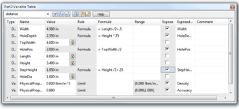
Solid Edge also enables you to use equations to drive dimensions. Equations can be entered using the Variables table. on the Tools tab, Variables group. The Variable Table looks as shown below:

This table is very convenient, and after experience with other CAD programs, I can say that entering equations and naming variables as well as “exposing” variables for use as custom properties is highly convenient. Plus, this dialog box can stay open while you do other things. If you’ve only ever used Solid Edge, maybe you don’t appreciate this as much as some other CAD users do. It’s not sexy, or shiny, or do spins or run robots, but this dialog is one of dozens of functions that are evidence of how focused on productivity these guys are.
And, more to the point of this post, the Variable Table dialog shows just how far you can take parametric functions in synchronous parts. Of course the parts I’ve used here are simple, but the concepts can be applied to anything you can drive with dimensions.
So if one of those CAD users who doesn’t know his CAD system is history tries to tell you that Synchronous Technology isn’t even parametric, you can just send him over here for an education, or sit him down and show him yourself.
If you want to experiment with some of these concepts on a part where the equations are already set up, you can download my simple sample from the button below.