ST7: Hole Options Dialog
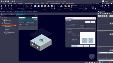
The Hole tool is another of the most popular enhancements in the ST7 release. The new Hole Options dialog is more visual, offers more settings, and offers options for the function of the hole (screw clearance, drill size, or dowel), in addition to the saved settings many users have relied on until now.

The icons at the upper left of the dialog seem a bit misleading to me, since you will never see a drill point at the bottom of a screw clearance hole, it would always be a through hole. The hole extents description of “Finite Extents” sounds a little funny to my ears. In standard hole parlance, this would just be a “blind” hole, but I guess this is long established Solid Edge terminology.
The “Sub Type” drop down list part of the interface may be a little confusing at first. For every type of hole, the Sub type selection will allow you to select from various options for the function of the hole, the type of thread, the type of screw or screw head.
The big image in the middle of the dialog that shows all the dimensions for the various features of the hole updates as you make selections for the hole type and depth.
 Make sure not to miss this little icon, right after the Standard drop down. This takes you to the database file for the selected standard. The database file is actually a spreadsheet that contains all the values that drive the hole geometry based on selections in the interface. If you want to change the values, change them in the Excel file, and save it. If you want to propagate those changes to others in your organization, overwrite the file for the appropriate standard in the location C:Program FilesSolid Edge ST7PreferencesHoles for a standard install of Solid Edge. In the past this sort of editing was not as accessible. Granted, you should not have to make edits of this sort often or ever, really, but if you find an error in the provided data or your shop just has a different way of doing things, making the edits will be easy.

Notice also that you have the option to drive the sizes for close, normal and loose fits.
The Threads area in the dialog only opens up when you have selected the Threaded, Counterbore, or Countersink hole types at the top. Again the values that automatically populate this area come from the database for the selected standard. Pay attention to the diameter type selection note – your selection in this area controls the diameter of the hole shown on the model for a threaded hole. If you have been doing this type of work in Solid Edge for some time, this might require a bit of retraining, but I hope you’ll agree that consolidating all these settings here is a good thing. I haven’t yet done a project that made a big use of hole features in ST7, but I think the more graphical interface is going to be easier to use, especially for new users. If you already have a lot of saved holes, you can continue working with those. The new interface and the new database give Solid Edge users a level of control over their hole features that you haven’t had before. For some people, this may well wind up being a top new ST7 enhancement.
Comments