ST6: Splines and Keypoint Curves
Spline Control
Splines are an integral tool when it comes to swoopy product design. For many users who are accustomed to more prismatic designs, splines can be a frighteningly uncontrolled way of working. ST6 has added some methods for controlling and evaluating splines.
The first enhancement I’d like to talk about are the Curve and Polygon Edit Points. The curve edit points are the points that are directly on the curve that you can move around to change the shape of the spline. ST6 has colored these red so you can distinguish them from the polygon edit points

You can control these colors using the Solid Edge Options > Colors, shown below.

Notice that the polygon edit points are always on the convex side of the spline. When the “polygon” (it’s only really a polygon when the spline is a closed loop) switches sides, the edit points change colors. So you’ll notice that by default the edit points on one side of the spline are light blue, and on the other side they are dark magenta. If all of your polygon edit points are on the same side of the spline (which only happens if the spline never flips convexity), they will all be the same color.
 Some people prefer to work with splines only using polygons, some prefer to use the curve edit points. Most people who have a lot of experience with splines prefer to use the polygon points. I personally use a combination, depending on the type of edit I want to make. If I need the spline to go through a specific point, I use the curve points. If I’m trying to change the curvature of the spline, I use the polygon points. One of the nicer new functions of the polygon edit points is that they can auto-attach to other geometry when you drag them.
You can make relations between control points as well, by selecting the tool on the Relate group, then clicking on the spline itself, and then selecting two control points to relate to one another. Another itemthat may not be obvious is that you can apply a driven dimension directly to the spline that displays the local curvature with a radius value. As you move the dimension along the spline, its value will change to reflect the local radius. This is not for length, or distance between control points, but just for instantaneous curvature at any point along the spline. It is a read only dimension, changing its value will not change the shape of the spline.

You can also use the CommandBar to control a lot of options of splines. To get this to show up, just select the spline itself. Notice that the control points are not displayed if the spline is not selected.
Key Point Curves
Ok, let’s call a spade a spade here. If the “curve” feature is really a 2D spline, the “key point curve” is really a 3D spline. Identifying things this way just makes it easier for me to know when to use which tool. I’ve been learning a lot about the software the last few weeks, and hope to continue to learn more. Most of that learning has been by making mistakes. One of the things I had to learn was that Synchronous Key Point Curves cannot be edited, while Ordered Key Points can be edited. This throws a wrench in my plan to put all sketch data in Synchronous mode, if I plan to use key point curves.
And here’s another tidbit about key point curves. If you just start sketching a KPC plinking down points in blank space, those points will all lie on a plane parallel to the screen orientation. Let that sink in a little. This may be the only time when the geometry you create depends on the angle from which you view it. And that plane will change if you rotate the view, putting a bend in the middle of a KPC with a few points made from one point of view and a few points made from another. Of course, things will also change if you click on a “key point”, which snaps that point of the curve to the key point. This is one of those things that might require a more detailed post later on.
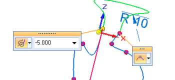
 Key Point Curves also have several enhancements in ST6. You can now create curvature continuous end conditions on the KPC. If the curve goes the wrong way (180 degrees from the tangency direction you want it to go), you can put a negative sign in front of the weighting number. The weighting number is also new, called a Numerical Magnitude Control. The handles at the ends of the curve shown in the image below allow you to change the end condition (when the KPC is attached to another curve or edge at the end) between Natural (no control), Normal to Face (in 3D), Tangent, and Curvature Continuous.
 In the image, the red line is the magnitude control, drag its length to “stiffen” the tangency or curvature at that end.
Key point curves can be used for a number of things, mainly any time you need a 3D curve. What are some things you have used key point curves for?


Comments