ST6: Holes, Threads, and Pattern Recognition
 In order to talk about Hole and Pattern Recognition, I have to first talk about Hole features, and we might as well pick up Threads along the way. You can find the Hole icon on the Ribbon on the Solids group. The Hole icon has a dropdown that includes Hole, Thread, Slot and Recognize Holes.
Holes
The Hole feature creates Simple, Threaded, Tapered, Counterbored, or Countersunk holes as features. These are editable as holes in both Synchronous and Ordered modeling. If you are used to some of the other CAD packages out there, ST6 does not have a list of standard screw sizes from Machinery’s Handbook. Solid Edge requires you to enter these values on your own. You can save all the various sizes you use frequently to reuse them so you don’t have to enter them a second time.
Threaded holes, however, do come with a list of inch and metric thread sizes, and callouts are added to the feature. For example, a 10-32 UNF hole is actually created with a .156” dia hole, which is close to the .159” tap drill size cited in my Machinery’s Handbook #27 (pg 1934). If this won’t work on your drawings, you can change the value in the Holes.TXT file found in your Solid Edge installation directory in the Preferences folder. Before you mess with this file, make sure to save a copy as a backup, and use comments to flag changes from the original. Be sure also to restart Solid Edge after making any changes to this file. The format of the data in the file is easy to understand and explained inside the file itself.
 Changes you make to Holes.txt won’t update any existing holes, but new holes will use the new values entered. This file only covers threaded holes (and threaded protrusions). Other hole types (such as counterbored or countersunk) do not have standardized sizes assigned by Solid Edge, as mentioned earlier. (In case you’re wondering, yes, this would be a great point to add an enhancement request).
Threads
Threads can be applied to any internal or external cylindrical face using the Threads command (Home >Solids>Hole>Threads). Solid Edge will again use the Holes.txt file to size and classify the thread. A couple of tips are in order here. First, do not apply your own dimension to the cylindrical face, it will interfere with the function of the command. Second,the cylindrical face for a female thread must be modeled to the internal minor diameter as specified in Holes.txt. The cylindrical face for a male thread must be modeled to the nominal diameter.
Hole Recognition
 Hole recognition was added to Solid Edge in ST5, but I’m including it in this discussion with ST6’s Pattern Recognition because the two topics really go together. In order for Solid Edge to perform a Pattern Recognition, the holes that you want to put into a pattern must be in a hole feature first. So if you get an imported part with a pattern of holes and you want to edit the pattern or the holes, you must first run hole recognition, and Solid Edge will place the geometry in one or more hole features, grouping identical instances into a single feature. Then you can edit the holes, and change all of the holes in a single feature to a different type of hole. For example, change 10 identical counterbored holes into 10 identical countersunk holes. You can change any of the hole parameters, such as cbr depth, diameter, and so on.
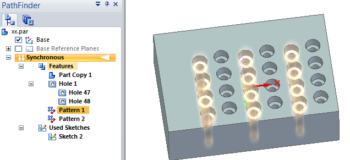
After the hole is recognized and edited, you can recognize and edit the pattern or multiple patterns. You can find the Recognize Pattern tool in the Pattern group. For example, below is an imported part. Solid Edge recognized all 24 holes as a single hole feature, since they are all the same. Then Pattern Recognition saw two different patterns. I tried to get it to make a single pattern of two holes, but I wasn’t able to do that.
Pattern Recognition
If you are trying to recognize a pattern, and the icon won’t light up, one of two things is probably wrong. First, you might not have any hole features, so go through the Recognize Hole step. Second, you might not have anything selected. It’s best to select the hole collector (the entry at the top of the list of holes – this could be less confusing by using a different name or icon for the collector). If you select one of the holes listed under the collector, the icon lights up, but the interface for the function does not fully appear.
 After the patterns have been recognized, the collector for this particular part only shows two hole features, and two pattern features. It shows two hole features because there is one seed feature for each pattern. It would be convenient in cases like the one shown here to have two seed features for a single pattern, but that may be an enhancement for a later release.
Summary
ST6’s new patterning and pattern recognition are slick. Combined with last year’s hole recognition, you’ve got some great tools for making native changes to imported holes and patterns. I’d like to put some standardized hole sizes on my wish list for the Hole feature for next year.