Solid Edge Tips and Tricks #9
 How can I turn the centerlines off in a view? There is no single button to turn off all center lines at one time. However you can create a query to find and select all centerlines, then uncheck the Show box that will turn them off.
- In the Display tab of the Drawing View properties, go to the Parts List options and select List Centerlines.
- Select New Query on the bottom of the dialog
- Give the query a name
- Change the property to Component Type, leave the Condition to Is Exactly
- Change the Value to Centerline and click Add to List.
- Click OK to save the query
- Click the Execute Query at the bottom middle of the dialog. This will find all of the centerlines.
- Now you can uncheck the Show button and update the drawing view and you are done. The query is saved on a “per file” basis, so you can use it on other views, but it will not show up in other drawings.
 How do you select multiple occurrences of the same part in the ST7 ‘Replace Part’ command? When you are in the ‘Replace Part’ command make sure ‘Occurrence Selection’ option is selected on the ribbon bar. This will select all occurrences of the same part for replace operation.
How do you bind all sub-assemblies within an assembly so they can be exploded with the Explode command? The Explode command does not have a bind option, so the sub-assemblies must be bound before running the command. Here are the steps:
- With the assembly open, go to ERA
- Click the Select Tools tab in Edgebar
- Click the New Query
- Enter a query to find all assemblies in the file: Query Scope: All Parts in Assembly, check the option to Search Subassemblies.
Property: Name Condition: Contains Value: *.asm Click Add to List. Click OK.
- Run the query by double-clicking it. All sub-assemblies highlight.
- Hit the Bind command in the Modify group in ERA. This binds the sub-assemblies
- Run the Explode All the sub-assemblies are treated as a single element to explode.
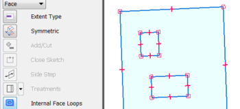
 How do you get rid of internal “holes” when extruding an imported profile in synchronous? After importing the DWG geometry in synchronous part use the “Extrude” command with the option “Exclude Internal Loops”. If you do this it will only extrude the outermost shape.
Why is the text for my coordinate dimension not changing orientation when I change it on the Text tab of the Dimension Style (or Properties) Dialog? New to ST7, the coordinate dimension text orientation is now controlled by its own Text Orientation field on the “Lines and Coordinate” tab of the dialog.
How do you find the Area of a void in a model, such as a hole, or cutout? – Perform the following:
- In the model, go into sketch and use Area, under Inspect
- Select the void or empty area
How do you turn off the Common Origin (dot) on a Coordinate Dimension? – Perform the following:
- Click the Style command and then select the Lines and Coordinate tab (View>Styles>Modify>Lines and Coordinate)
- Under the Coordinate group/section click the drop list for the Common Origin and click your preference, in this case None
- Click OK

Why are my Saved Settings for holes not showing up in the list? Make sure you are pointing to the correct settings file. First, open a part file, then go to the Application Button, Solid Edge Options, File Locations page, and select the Custom Settings File. Click Modify and browse to where your custom settings file is located (usually on your server).