Solid Edge Tips and Tricks #6
Why am I getting an error pasting clipboard geometry to its original location?
In earlier versions of Solid Edge like V20 when you copied geometry to clipboard and paste it back, the copied geometry was automatically placed in its original location. But in current versions the geometry is attached to the cursor and you have to click to place it. If desired,  you can change the default behavior by setting the following option in “SE Options/General tab/Preferred 2D Paste Behavior (Draft, Ordered Sketch/Profile)” to “Paste to original position” OR “Paste to selected position”. You can also override the default behavior on the fly during the paste operation by selecting one of the following commands: “Home Tab/Clipboard Group/Flyout arrow under Paste/Paste to original position” OR “Home Tab/Clipboard group/Flyout arrow under Paste/Paste to selected position”.
Can I export to dxf without including the drawing sheet background?
Yes. Uncheck the “Translate background sheet on export” option on Step 1 in the AutoCAD Translation Wizard.
How can I orient a reference plane to the opposite side?
If you are creating a coincident or parallel plane by selecting one of the Base Reference Planes, it will always orient itself to the plane it is based on; however, if you turn off the base planes and turn on the base coordinate system, a reference plane from the base coordinate system is oriented by the window orientation. So if you rotate your view around and look at the orientation you wish for your resulting plane, just select one of the planes in the coordinate system.
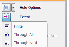
How can I change a synchronous hole from through hole to finite in a drawing view?  Select the hole in the Pathfinder. Click on the hole label on the view (blue text). This will open the command bar. Select the Hole Options. This is the second button in the command bar. Look now for ‘Hole extents’. Here you will see the ‘Hole Extent’ button.
Is it possible to set all levels of my assembly to Simplified?
Yes. Hold down the Ctrl key and then right click on the top level assembly and select Use Simplified Assembly and it will cascade down the entire tree from the selected level. This same process works with setting to Designed as well.
How can I migrate materials from ST6 to ST7?
Copy the ‘Materials.mtl’ from ST6 to the following folder in ST7: C:Program FilesSolid Edge ST7PreferencesMaterials OR to the corresponding Materials location in case you have customized it.
How can I change the color of a sketch display outside of sketch mode?
When you get outside of the Sketch/Profile mode the sketch elements are treated as wire bodies. So the color associated with it is not what you see inside sketch or profile. You can actually change the color of wire body display by using “Part Painter” command.
- Go to “View tab/Part Painter”
- In the ribbonbar for this command set “Style = Red”, “Select = Any”
- Select the sketch
- Close. This will change the color of the sketch display.
Why is the Quick View Cube not showing up in my Solid Edge window?  The Quick View Cube will only display using high end graphic display settings, please ensure that the ‘Graphics Card Driven (Advanced)’ option is selected.
What is “Bump bending” and how does Solid Edge do this?
“Bump bending” is a slang term for linear bending in increments to emulate a rolled part. Bump bending generally implies multiple hits in the press brake to achieve a large arc type bend to achieve similar results that are attained in rolling. If this is the case the only thing we do to match that is to have him use Add Bend multiple times, or more effective would be to use the “Bending Method” option on the Lofted Flange command and use to cross-section sketches to determine the shape, then use the option to determine the number of hits, or bends.
How do I show a scale caption for my drawing views?  To show the view scale as a caption for a drawing view in Draft do this:
- Right-click the drawing view and go to Properties
- Select the Caption tab
- In the Caption Section, Caption Type should be set to Primary Caption and the Show box to the right of the field should be checked.
- Still in the Caption Section, click the View Scale button in the row of buttons under the white text box. It should add the string %VS to the box.
- This is the Property Text string for View Scale.
- Under the Properties Section, Check the Show box on the View Scale line.
- This will turn on the display of View Scale caption.
- Click OK or Apply to see the changes.


