Solid Edge Design Optimization using Excel Solver
This articles discusses about:
• How to drive a Solid Edge part from an Excel Spreadsheet.
• The Excel Solver Add-In.
• Using Solver for design optimization in Solid Edge.
The Scenario
I am contacted by the design office of an aluminium can manufacturer. They supply around 60,000 cans per week to the local soft-drink bottling plants. The cans are made of premium quality aluminium sheets, so raw material is a concern. Also, the minimum volume to hold is 300 ml.
The Excel Solver Add-In
First of all, I want to introduce you to the Excel Solver. It is an add-in that comes with Excel. It is not installed by default, so chances are you may not have it if you did a Typical install of Excel. There is an easy way to find out.
Start Excel and look in the Data tab – Analysis group.
Solver should be listed with an icon that looks like a blue question mark with an arrow.
Another place to check and if required install is under Excel Options.
To view Excel options, just as in Solid Edge, click Excel’s Application icon and select Excel Options at the far bottom side of the menu. Take Add-Ins form the panel on the left. Under the Manage list, select Excel Add-ins and click the Go button.
Solver sould be listed in the available Add-ins. If not, click the Browse… button and locate the file LibrarySOLVERsolver.xlam from under the folder where MS Office is installed on your system.
In the worst case, ask your IT administrator to run the Office setup again and install the Solver Add-in for you.

Problem Definition
As shown in figure, enter a few labels and values to describe the parameters of a can (cylinder). To begin with, enter arbitrary values like 5 for the radius of can and 12 for height.

The radius and height are plain values, while, the volume and surface area are formulas.
The volume of cylinder is given by :
v = pi . r . r . h
and surface area by:
a = ( The curved surface ) + 2 ( cap surface )
therefore,
a = (2 . pi . r . h) + 2 . (pi . r . r )
Accordingly,
The formula in cell B4 ie. for volume will be =3.14159*B1*B1*B2
And that in cell B5 ie. for surface area will be =2*3.14159*B1*B2+(2*3.14159*B1*B1)
This will result in 942.48 for the volume and 534.07 as surface area.
We want to minimize surface area for a volume of 300 by varying both the radius and height parameters to their optimum values.
Design Optimization
Since, raw material (aluminium sheets) is to be kept minimum, surface area for the can should be minimum. This is the target.
Also, volume of cylinder should not be less than 300 ml.
This is the constraint.
We need to vary the radius and height of the cylinder such that surface area is minimum and at the same time, volume should always stay above 300 ml.
The Excel Solver also speaks in terms of targets, constraints and variables.
Let us see how…
Specifying the Target
Assuming that you have entered both the formulas correctly, proceed as follows…
1. Start the Solver and when the Solver Parameters dialog appears, click the small cell-picker shown with label 1 in figure.

Balloon 2. The dialog turns into a thin stripe. Select cell B5 for the surface area as shown in figure and press <Enter> at the keyboard.
Balloon 3. The address of the cell appears in the Set Target Cell area.
Balloon 4. Next, click the Min radio button.
In the four steps above, we have told Solver that the target is the surface area which is to be kept minimum.
Specifying the Variables
1. Click the cell-picker for By Changing Cells as shown in figure below:

2. The dialog turns into a thin stripe again and press and drag to select the range B1 to B2 and press <Enter> at the keyboard.
3. The range labels appear in the textbox to the left of the cell-picker.
In the three steps above, we have specified the variables
Specifying the Constraints
1. Click the Add button in the Subject to Constrain area.

2. The Add Constraint dialog box appears.
3. Again click the cell-picker for Cell Reference and select cell B4 for the volume. Press <Enter>.
4. From the drop-down list, select >=
5. Finally, in the Constraint textbox, type 300
6. Click OK
In the six steps above, we have specified the constraints.
Back to the Solver dialog, click Solve and then click OK for the keep solution option.
The radius and height are calculated for volume >= 300 and minimum surface area.
The next few steps illustrate how to link the radius and height cells to a Solid Edge part.
So keep scrolling …
Preparing Solid Edge
Launch Solid Edge and in a new Ordered Part create a cylinder to represent the soft drink can by extruding a circle that has a Radius dimension applied. When applying the Smart Dimension to the circle, switch to the Radius mode from the command bar.

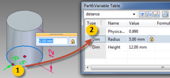
Select the Tools tab and from the Variable group, select Variables.
Using the Select Tool on the Home tab, pick the radius dimension. The row for this parameter will be highlighted in the variable table as shown below.

Select the name and type Radius for the variable name as seen above.
Tip from the Edge: Renaming variables to more meaningful ones though not absolutely necessary even in the present case, is a good practice.
Putting it all Together
Using Windows + Tab, switch to Excel.
Copy the radius value by right-clicking in the cell and selecting Copy from the menu.
Swich back to Solid Edge and in the variable table, right click in the radius row and select Paste Link (not Paste) from the context menu appear that appears.
In case you get a ‘source is invalid error’ save the Excel file and Copy-Paste Link again.
The cell address from Excel is now linked to the Radius’ Formula in Solid Edge.
Observe the formula for the Radius in the variable table:
@‘C:FolderNameExcel_Solver_SE.xlsx‘!’Sheet1!R1C2‘
The @ symbol as in an email address.
Full filename with extension and complete path.
Sheet name
Row and column numbers.
– Not just tightly coupled but so neat and clean !!
Not just that, the Formula cell in the variable table is smart too.
Doule click in it and it will (if Excel is not running) launch Excel and also open the workbook for you.
Save both the Excel workbook and the Solid Edge part document preferably in the same folder and you are done. The cells and the part will be linked together and remain to be so happily ever after…
Precautions and How to Use
1. Always open the Solid Edge Part first.
2. Make sure, the Automatic Update button found under the Tools Tab’s Links group, is turned ON.
3. Pop the the variable table and right-click anywhere in it except on the column header and select Edit Links from the context menu.
4. In the Links dialog, select the required Excel file and click the Open Source… button. This will launch the Excel document. This also necessarily means values from various cells from different sheets in multiple Excel files can be used to drive a part.
5. Once in Excel, start Solver and click the Add button. Specify a new constraint. Click OK and marvel at how the new optimized values for Radius and Height percolate down to the model which updates in real-time.