Solid Edge 2022 User Perspective: Design Configurator


Editor’s Note: This article is the third in a series of articles independently authored by Scott Wertel, a design engineer for Aerospace Research and Development Group, LLC.
I wish I had this 20 years ago
As a machine designer, I was often tasked with joining the sales team on a client visit. That was never my favorite part of the job, but I learned a lot and gained a lot of respect for what the front-end Sales and Application Engineers had to go through. What I disliked more than that role, though, was the one just after the sale closed and the proposal got sent to Engineering. “YOU PROMISED THEM WHAT?! AND THEY’LL HAVE IT BY WHEN?!” was often the start of those conversations.

And the reason the second meeting was worse had to do as much with the type of business I worked in as it did with overpromising. The company I worked for not only designed the machines, but we designed the entire production line for the client. They gave us a floor plan of their current factory layout, their throughput requirements, and we designed the machines and conveyors and accumulation stations and did all the math to ensure the entire production line met their goals. You can imagine being a Sales or Application Engineer and having to not only be able to explain our products (which were engineer-to-order machines), but also understand production operations. And that’s why I’m excited about the new Design Configurator feature from Solid Edge.
Not like other configurators
There are other MCAD tools out there that have a product with “configurator” in the name. And while they are designed for the front-end conceptual phase of the sales process, they often fall short when it comes to converting those concepts to the back-end design and engineering. I’ll be honest, up until Solid Edge 2022, there was only one other MCAD package that I would get excited about for machine design, and it wasn’t just because of their Triball. It was because, until now, they had the best configurator on the market. I would even recommend them over Solid Edge to clients that did the same type of machine design and plant layout that I had done in the past (on the drafting board cutting and taping shapes of machines and conveyors, no less, trying to get them all to fit on the page).
I have often tried to imitate rules-based design by creating elaborate functions within the CAD tool’s equation editor, even within Solid Edge. While this works for simple families of parts, it doesn’t work for more complex systems. This is the limitation I’ve seen with most configurators built into CAD tools.
And while there are other specialty tools that do an amazing job, also using names like Configurator, Options & Variants, or Product Line Engineering, Solid Edge 2022 has the only design configurator that is integrated into the CAD solution with the same power as those rules-based specialty tools. So enough with the story telling, let’s take a closer look at Design Configurator in Solid Edge 2022.
Rules-based automation
Developing a baseline understanding of rules-based automation will help in understanding why I’m so excited about Solid Edge Design Configurator. Those other so-called “configurators” were merely a lightweight CAD tool that allowed front-end sales folk an easy way to drag and drop in catalog parts into an assembly to show the customer what was possible. There was no logic or “rules” behind what the salesperson could or could not do. Often, the result was something not feasible. Thus, the dread that happened in the second meeting when Engineering had to pull off the impossible because the customer had already seen it during the sales meeting and solidified their expectation.
The rules-based systems avoid this issue because, as the name implies, they have rules that determine the possible configurations. You often see this type of specialty tool employed by large manufacturers (like automotive or aerospace) with many custom options on their products. This saves Engineering time because they don’t have to design every single potential configuration, while still maintaining control over the options and variants. And the sales team can feel confident that they are showing the client something that the Engineering team has already pre-approved. But those specialty tools, while worth their weight in gold for those applications, cost a premium and are often out of reach for the mid-range market as well as being quite complex to use. Sadly, the need for them is not out of the range of the mid-range market, which is why having this available in Solid Edge 2022 is game changing. (Yes, I said it. Sorry.)

Why rules-based configurators are needed
From fasteners to product catalogs to engineer-to-order, there are many examples of families of parts or product models that are all derivatives of each other. I would argue that very few products are revolutionary, rather they are evolutionary derivatives of a previous product. And because they are evolutions of that product, the baseline part can be used with only a few tweaks to the design to create the next variant. For simple products with little more than a dimension change, equation editors work just fine. But for more complex systems, there are more requirements that must be considered.
Take a conveyor belt as an example. I designed many conveyors in my past. While they look simple, they are anything but. Depending on the product being conveyed, there are speed and acceleration limitations, turn (or bending) radii limitations, and overall length limitations. If I must convey a package across an entire warehouse, that could be hundreds of feet. But my raw material is shipped on a flatbed truck and, unless I’m ordering a special mill run, must be no longer than that. I may also have storage or machining capacity issues. In my history, we could only handle metal bars as long as 8 feet in our machining centers. Any conveyor longer than 8 feet had to be spliced together. And of course, there are rules to make sure the conveyor can fit through the door. I can’t tell you how many times I took those paper cutouts and slid them from the overhead door (on the floorplan layout) to the final assembly location, around support columns and existing equipment, to make sure we could get the equipment in the door, much less install it. (This was before there was such a thing as virtual assembly.)
Length, width and height – simple, right?
With some of those limitations in mind, let’s take a closer look at designing a conveyor to illustrate why rules-based configuration is needed.

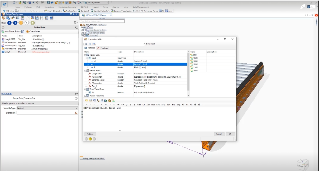
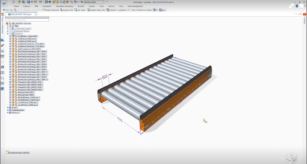
We have a conveyor of a standard width. In this case, 425mm. What if the customer wants 450mm? Well, rollers are off-the-shelf components. The vendor only stocks certain lengths. We can create a rule to allow conveyor widths aligned with stock roller lengths. This rule gives the sales team permission to show the customer any of the “stock” width conveyors that we could offer even if they haven’t been designed before. The sales team could deviate from that rule, and the rollers could be custom ordered, but that would add lead time and extra cost for a custom length roller. The sales team would know that ahead of time and therefore would be able to inform the customer of the expectation.
The pitch of the conveyor is 60mm in the example above. As before, the rollers are off-the-shelf products. They come in different diameters. A rule could be created to that would automatically adjust the pitch based on roller diameter. This, in turn, affects the number of rollers over the length of the conveyor as well as the cost of the conveyor system. Again, this allows the sales team to accurately define the product with rules that have been pre-approved by Engineering and set a proper expectation for the customer. It also starts to highlight the complexity on how a single variable change can have multiple impacts on a design – something difficult to control with equations alone.
The conveyor length is not clearly shown in the example above, but let’s say it is our standard 8-foot length. More accurately, a rule is setup that makes the total length an increment of the pitch not to exceed 8 feet. The parametric CAD model has the ends of the conveyor setup that any splicing or mounting features automatically adjust based on the length and pitch variables. And because we can determine the weight of the product being conveyed, we know how many supports need to be mounted to the conveyor to support that weight. Another rule, which drives the parametric CAD design to only create mounting holes/features as necessary which reduces excess machining time and cost.
Start designing with rules
Maybe simple really isn’t so simple after all. I hope you can see, based on my example, why rules-based configurators can be so valuable for the entire engineer-to-order process – from sales to final installation. While some parametric CAD features can certainly be designed with elegant equations, there are often many variables (aka rules) to consider, and a specialty tool is required. Having a design configurator embedded within the CAD package is rare, and that’s why I’m excited to see it in Solid Edge 2022.
I know I focused a lot on the front-end sales side of using the Design Configurator, but please understand that these rules apply to design as well. In other words, design once, create rules, automatically generate all derivative configurations. How much time will that save you?
You can learn more about Solid Edge 2022 and Solid Edge Design Configurator here. It’s only coincidental that we both use a conveyor as our example. Or maybe it’s because they are not as simple as they appear.
To learn more about what’s new in this release, visit siemens.com/solidedge2022.
About the author
Scott Wertel, P.E. is a freelance design engineer at Aerospace Research and Development Group, LLC. He’s an avid Solid Edge user and hasn’t been this excited about a release since that one where they did nothing but fix all the bugs.
Contact: scott.wertel@aerornd.com

Comments
Leave a Reply
You must be logged in to post a comment.


Great stuff, Scott.
Ilogic reading this topic be like: looooool hello from 2009