Simplify your modeling process, and reuse existing design data

A look at some core design techniques including top-down design, applying synchronous technology and reusing design data is the focus of the 15th webinar in our Solid Edge Digital Transformation webinar series. This webinar replay may be of more interest to designers who are fairly new to Solid Edge or those who want to learn more about these core design techniques.
After a brief overview of how manufacturing companies can undergo a digital transformation and speed their product development process, the demonstration starts at 5 minutes into the webinar replay. Kevin Grayson conducts the demonstration and the first area covered is top-down design, how designers can model new components in the context of an existing design, ensuring they are positioned correctly and match up with existing components. The demonstration shows how designers can tag locations on existing geometry and quickly create a sketch as their starting point for a new component. They can add constraints and dimensions to the sketch to capture their design intent and then extrude a 3D model from the 2D sketch. Using synchronous technology, dimensions from the 2D sketch are automatically transferred to the 3D model. As shown in this demonstration you can even delete the 2D sketch at this stage! In other CAD systems this would lead to deletion of the 3D model but this is not the case in Solid Edge. The Design Intent dialog is displayed to show how the designers thought process has been captured by Solid Edge, for example recognizing that the new part should be symmetric. In this demonstration a change to the hole on one half of the design is automatically reflected in the other half of the design. Top-down design process: 1.Tag existing 3D geometry 2.Create a sketch 3.Extrude to 3D 4.Display in assembly and make final edits
When the original assembly is displayed we see that there is some interference, using synchronous technology it is easy to grab a face of the model and push it to remove the interference, and you can also add a dimension to make this change in a more precise way. As there are many different ways in which you can modify 3D geometry, the Steering Wheel is used to specify the specific type of change you want to make. In this demonstration it is used to change the angle of one of the faces. Another useful tool, especially if you are moving from another CAD system to Solid Edge is the Command Finder, here you can input a term that you used in your previous CAD system, for example “hollow”, Solid Edge then finds the equivalent commend (“thin wall” in this example) and even highlights this command in the ribbon bar. And you can also reuse complex features that you previously defined in another design and place them in your new design, in this example a set of ribs are placed into the new component.
 Using the Command Finder to find the capability you need – even by using terminology from other CAD software
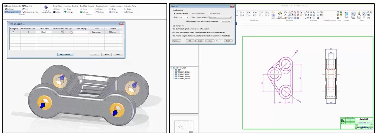
In the final part of the demonstration, a 3D model and a 2D drawing from different CAD systems are used to complete our design. This is a common requirement as you may need to incorporate catalog parts that are only available in a different CAD format, or you have a large amount of legacy 2D drawings that you may need to access and reuse. When importing a 3D model from a different CAD system you can use commands like Recognize Holes and Recognize Chamfers to import specific gemotery and add them as intelligent features in the Solid Edge Pathfinder. And for 2D geometry, the Create 3D wizard guides you through the steps to create a 3D model using the profiles and dimensions from the original 2D drawing. Synchronous technology again comes in to play in this process as the dimensions jump from the original 2D drawing to your new, intelligent 3D model.  Two great ways to reuse existing design data: 1.Recognizing intelligent features in imported 3D CAD data 2. Creating 3D models from legacy 2D drawings
The two new components are placed into the Solid Edge Assembly and some final modifications carried out after using commands to check interferences and to move the assembly components through their range of motion. Fasteners are placed from built-in library of standard fastener assemblies to complete the design.
This webinar in just one in a series of 15 webinars covering a wide variety of topics, register here to watch the replay of this design techniques and you will get access to all 15 webinar replays!


