Schematic Diagrams in Solid Edge
Schematic diagrams are one of the purely 2D functions that make Solid Edge such a full-featured CAD program. There are a lot of people who use one program for 3D and another one for 2D. With Solid Edge this isn’t necessary, as one program does it all.
The research for this article was done from two primary sources: There is an Ally PLM Lunch Byte video on the topic, and a Solid Edge tutorial you can find through the Help. Neither one  really had all the answers, but the tutorial answered more “how” to do it, and the video answered more “what” can be done.
Schematic diagrams in Solid Edge are created in draft documents, and use items called “connectors” to connect blocks. You can associate text properties with your blocks to annotate your diagram automatically to some extent. Connectors snap together, and are more intelligent than just drawing lines. Solid Edge blocks work just like most other 2D blocks, but they have some special properties. Let’s talk about blocks first.
Blocks
Solid Edge installs with a lot of standard blocks. Blocks can be saved as independent *.dft files, the same extension as standard draft (drawing) files. Blocks can also be used directly from any existing drawing, or they can be saved together in a single *.dft file, making libraries of blocks very easy to create, which is far easier than just saving each block as its own file.
The default path for your Solid Edge blocks is C:/Program Files/Solid Edge ST6/Sample Blocks. In this location you’ll find electrical, mechanical and piping blocks.
If you’re new to Solid Edge,  keep an eye on this Library I’m about to explain, because its an important difference in how Solid Edge helps you find data you need more quickly. You can use it for parts, assemblies, and blocks, among other things. You can treat it like a window of Windows Explorer right inside Solid Edge.It’s very nice once you learn to use it.
 One thing about using the Library with certain other interface items. I’m using the vertical docking Command Bar. When you do this, the Library and the Command Bar might be set up to share the same space. Notice in the image to the right that the Library tab (next to last) is active while in the image below the Select Command Bar uses the last tab.
You don’t really want to have these things overlapping, at least I don’t like it. Either the software is switching, or you’re switching, and it’s just not nice. So here’s what I do in Solid Edge draft.
 Grab that icon on the right and drag it off the row of icons. Now you can put it anywhere you want. You can dock it back to the left side, dock it under the Library, where ever. Experiment with where you want to put it. If you drop in on the center dot in that cluster of four arrows, it will go right back where you had it. This to me is excellent and extremely flexible interface design.
Since we’re already off track, here, let’s keep going. Remember that Solid Edge is going to remember your interface layout for each environment, and you’ve got environments for parts, sheet metal, assembly and draft. Once you get one environment set up, it will stay that way, but you may have to set up another environment the  first time you go there.
Getting back on track, set up the Library window by clicking on the Library tab (row of icons under the orange Library header, next to the right end) and then click the Show Blocks icon (next row of icons, left end). Then use the panel right below the tab icons (labeled with the name of your C: drive) to navigate to the sample blocks folder identified earlier. Browse to one of the block folders, say the Mechanical folder. Then click on the first item on the list, Fluid Power Components and Basic Symbols.dft. This is just a draft file with a lot of blocks in it. The blocks in the file are listed in the window below, with the various Accumulator entries. In the bottom window is a preview of the block selected in the middle window. The Solid Edge interface is pretty densely packed, but it is very adjustable, and make sure to use the tool tips to help you identify things.
When you see a list of blocks, as shown above, the blocks may have one of two symbols. It might have four square boxes or four square boxes with a push pin. The push pin means that the block is used in your current  document. So in the image to the right, the top block is used in my drawing, and the bottom one is not.
To put these blocks on the drawing sheet, click and drag a block name from the text list. It will appear attached to the cursor when you drop it on the drawing. You might expect it land on the drawing at that point, but it doesn’t do that yet. You still have to orient it, then place it. To orient the block on the moving cursor, press A for 45 deg counter-clockwise, or S for clockwise. So the workflow for placing blocks is:
- drag text to sheet
- drop on sheet
- A or S to rotate
- click to place (does not snap to connector)
In practical terms, I’ve found its better to place the symbols first, then attach the Connectors to them. When moving items, move the symbols rather than the connectors. This is because there does not appear to be any way to attach a block to an existing connector (although you can do the reverse), and if you move the connector, it doesn’t move the block (again, the reverse does work).
We don’t have space in this article to talk about creating blocks, we will have to talk about that next time. For now, I want to shift to talk about connectors a little.

Connectors
You can find the Connector icon (make sure you’re in a Draft document) on the Home tab, Annotation group. Be aware that there is also a big Connector icon on the Diagram tab, Views group, but these are not the same thing.
Connectors are used to create the lines you would draw between the various block symbols on your diagram. There are four shapes of connectors:
- Line
- Corner
- Jump
- Step
 The Line connector, as the name implies is just a straight line. The corner has a 90 deg bend, the Jump allows you to jump one connector over another connector with a little hump, and the Step allows you to line up misaligned items with a pair of 90 deg bends. You’ll get the gist of working with these shapes in a minute or two of playing with each one.
Each connector shape in turn allows you to set if there is an item on the start or end of the connector. These items include arrows, dots, circles, anchors, and so on.
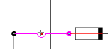
If you want to edit a connector once it is placed, just click on it, which will turn it pink and show the control points. To the right, I’m moving the hump for a jump to put it on the line connector (so the jump jumps over the line).
If you would like to start by inspecting an existing diagram, there is a sample automotive  electrical schematic installed at C:/Program Files/Solid Edge ST6/Training Files/seddasc.dft.
This will give you some idea of what can be done with this functionality. Remember that the symbols provided with Solid Edge are just samples, and you can create your own, or even import existing AutoCAD blocks. Regular Solid Edge draft views made from 3D parts or assemblies can coexist with schematic diagrams in a single draft file, although putting the schematic in its own separate view would be advisable.

I’ll be back in the next article to talk about how to create blocks with all the text properties as well as importing AutoCAD blocks for use in Solid Edge. How many of you out there use blocks for schematics in this way? Does anyone use a more purpose-built schematic tool (such as Visio)?


