Opposite-Handed Parts and Drawings
For this blog article, I admit, I’ve borrowed an idea from Dan Staples. About 6 months ago, a user was asking a question on the forum about how to make a mirrored part and a mirrored draft from the original part and draft. Dan’s answer was short, but I’ll have to go embellish a little by going through the steps and adding illustrations here. Here’s a link to the original conversation.
The story starts out that I’ve got this part I like, but it’s symmetrical left to right, so it won’t make a very good demo for left and right handed parts. If you’re anything like me, problems come to you in multiple levels, so you have to solve one problem before you can even get to the next problem. That’s my situation here today. I want to mirror this part, which I don’t know how to do yet, but to make that mean anything I have to apply some text, which I don’t know how to do yet either.
Ideally, text should be extruded in Ordered mode, unless you’re pretty confident that you’re not going to have to make any changes to it. Synchronous changes to extruded text can be done, but they are tedious. But I’m doing it in Sync mode. If I need to make a change, I’ll have to cut the text off the model and recreate it.
It just happens that I have never used the Text Profile tool in Solid Edge before. So great, I get to learn something today. And because I’ve got to do it, I’m gonna drag you along with me.

 First, the Profile Text is on the Sketching tab, over on the right end. I found it by using the Command Finder. It wasn’t the first thing in the list, sometimes you have to have a little patience with these search solutions.
So you click the Text Profile button first. Enter your text, change the font. Be careful with this, because unlike most Windows applications where text settings apply only to the selected text, here in Solid Edge Text Profile, it works inconsistently. Any font can be applied to the entire text or to a selection. But if you want to make something bold, you have to select it first, and set it to bold.
Next you click OK and you can place the text profile on a plane, like the planar face indicated in the image to the right. Once this text is in place, it has to be rotated. There’s no real obvious way to do this, and I was a little concerned about the box around the text, which I didn’t ask for, and didn’t know how to deal with.
 To rotate the text, I still don’t know how to do it while placing it. There must be a way. But after it has been placed, the interface all goes away, so just select it, and this Edit Definition box comes up in the CommandBar. Click Modify, then Move.
This will give you a Steering Wheel, which you have to reposition, and then use the torus to rotate 90 degrees. I just dragged the center handle onto a vertex on the flat face and the torus laid flat on the face.
Ok, so this let you rotate the text, but now you still have to move it. You can’t move it just by grabbing it with the cursor, you have to use a tool. So select it again, and go back to the CommandBar and use the Reposition tool to move it.

 Alright, so we’ve worked through a few issues there. One more to go. How do you extrude this? It’s not like a regular sketch. Being in Sync mode, I expected this to be pretty intuitive, but it’s not.
Switch back to the Home tab, in the Solids group, click Extrude. On the Extrude CommandBar you find this drop down that might be set to Face by default. Select Single.
Now you can select the text, and it extrudes, ignoring the box around it.
 There might be a couple of areas in this workflow that could be simplified or streamlined.
Anyway, I’ve done this twice, so now I have Solid Edge on one side of the part and Other Side on the other.
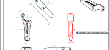
Fortunately, I already created a draft of the part with some views and dimensions on it, and I’m going to use this to create the opposite handed part first, and then the opposite handed drawing.

 The first step is to close everything down. The drawing, the part, everything.
- Now open a new part and use Insert Part Copy (remember this is on the Home tab, in the Clipboard group, click the Part Copy drop down).
TIP: Again, you cannot get a linked part copy in Synchronous mode. So you can use Sync mode only if you want a dead link (no link – just geometry). If you want a live associative link, you have to use Ordered mode). In this example I’ll switch to Ordered mode and go forward from there. I’ve included the Piston Rod part and draft at the end of this article as attachments if you want to follow along and do this on your own. - In the Part Copy Parameters dialog, under the big window is a Mirror Body option. Make sure that is turned ON, mirroring about the XY plane, with no changes to the scale. (notice when you do this, the text shows up backwards. This will help us keep track of which part is mirrored – yeah, right, it was intentional ;o)
- In Windows Explorer, make a copy of the draft file with a name you’ll be able to find. This copy still points to the original part. Open this copied draft document.
- In Dan’s instructions, he simply says to “use the Change Source” command, which is great, if you know where the Change Source command is. But I don’t. And it looks like the Command Finder doesn’t know where that is either. So a little web searching led me to an article that helped me find it. From the draft file,
App Menu> Manage>EditLinks, select the file name, and then Change Source becomes available.


 Click the Update Now button, and back in the main interface, on Home tab, click Update Views on the Drawing Views group.
- This updates the views, but some dimensions or callouts have become detached (dangling in Works speak), denoted by the same brown/khaki color. The R 21 radius dimension reattaches easily by selecting the dimension, then dragging the arrow connection back onto the appropriate edge of the view.
- The foreshortened dimension is not so easy. There may be an easier way to do it, but the way that worked for me was to remove the foreshortening, and make it a diameter dimension. Then I could reattach it and re-shorten it. (it turns out that these dimensions were broken before this mirrored draft exercise, and I was just fixing a problem I had created before when editing this part, thus the change from 400 to 200mm).
Finally, here we have a drawing (with the backwards text) of the mirrored part.
So this got a little more involved than just making a mirrored drawing, but when was the last time you had something to do where you only had to learn one thing? It never happens for me that way. Usually one problem leads to several others, and you have to solve them all to complete the original request.


Comments