Inspect Tools: Smart Measure
When I asked for suggestions for blog topics, one that came back was for an article on the Inspect Tools. It has taken a while, but I’m finally getting around to fulfilling that request.

It turns out that there are a lot of Inspect tools, and some of them depend on which type of document you are working on – parts, assemblies, or drawings. For this particular article, I’m going to start with the tools for assemblies. There is a fair amount of overlap with the parts tools, but there are fewer assemblies tools. I’ll come back and do a follow up article on the parts tools.

 Smart Measure
The most obvious is the Smart Measure tool. Smart Measure just gives you temporary measurements that only stay on the screen until you do something else. If you want a dimension that stays with the model, then I’d recommend using the Smart Dimension tool.
One of the things that may require some getting used to for new users or people from other CAD systems is that the dimension that you get is obviously dependent on the selection of items you want to measure between, but it is also very dependent on the angle from which you view the selected entities. So if you rotate the model while moving the cursor, the measurement shown will change.
For example, in the first screenshot below, I’m getting the overall width of the motor, while in the second screenshot, made with the same selection, you see an entirely different measurement.

This happens in other places too. If you are new to Solid Edge, you may look at this as an annoying difference between what you used to use and Solid Edge. But if you’ve been using Edge for a while, you recognize that it’s actually a very powerful  method for getting what you’re looking for.
When you click as if you were placing a PMI dimension, the measurement just goes away. Unless you have the “Create In Model” option turned on in the CommandBar. By the way, the proper way to make a second
measurement is not to hit ESC, that will cancel you out of the command altogether. The best way is just to click the right mouse button. That clears the selection and allows you to continue with another measurement.
Another thing you might notice is that you cannot measure from flat faces. Every edge is connected to two faces, so measuring from edges gives you more options. Also, there is no measurement that you can make from a face that you cannot make using the edges of the face. If you are used to something else, this is just a new method to get used to. It’s not a reduction in capabilities.
You can however, measure from cylindrical faces created by round (fillet) features, but you can’t measure the distance between parallel cylindrical sections of the pressure washer frame shown above. Selecting round faces enables you to measure from the virtual sharp (where the faces would have intersected at a sharp edge if the round/fillet were not there).


These two dimensions were both created from selecting the two purple faces. In the case of the 3 inch dimension, Solid Edge interpreted the selection as the virtual sharp edges, and in the 1 inch dimension, it interpreted the selection as just the endpoints of the virtual sharp edges closest to the selection point on the original surface. To get the 1 inch dimension, both purple faces were selected on their left ends.
Dimensions and measurements in Solid Edge may seem frustratingly arbitrary until you know some of these rules that are by no means obvious. Now that you know, though, you have a lot more flexibility for creating dimensions and measurements.
In addition to the dimension being controlled by your selection, the view rotation angle, and your cursor position, you can also press N (for next) or B (for back) to toggle through all the possibilities for the current selection. The dimensions below were all created by selecting the angled round face with a little highlighting on it.


Further, notice that Solid Edge uses dimension leaders in 3D. This helps make it clear what is being measured. The first and third dimensions above are actually the same, they are just being displayed differently.
 You can get this dimension, shown to the right (which is really the same as the second dimension above) by using the Lock Dimension Plane option in the Other panel of the Command Bar. To use this, lock the dimension plane first, then select the entity to measure. Again, this workflow isn’t at all obvious, and even the PromptBar doesn’t make it clear.
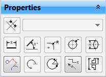
According to the Solid Edge Help, the Dimension Axis (upper left of Properties panel) is not available for the Smart Measure or Smart Dimension tools. Which of course begs the question “why is it there?”
If you want to create a dimension like the one to the right, as far as I can see, you can’t do this with a measurement, you have to use the “Distance Between” dimension tool. You might be able to use the 3D Measure tool called Minimum Distance, but that works in a completely different way from either dimensions or measurements.
Ok, at this point I’m going to have to ask for some input. I’m obviously confused. Could someone with some experience with this please step in and explain this?
My sample gas tank part is attached to this article, if you would like to use it for examples.


Comments