Imported Parts and Drawings
There are a lot of things I could call this article, but at its root it has to do with imported parts and drawings. The main feature I’m going to use is called Create 3D, which is perhaps a name that only partially describes what the tool does.
There are two main ideas here:
1. sometimes when you import a part, you would like to apply PMI dimensions to the model. The best place to get these dimensions is from the drawing.
2. You can build a 3D model from the 2D drawing.
To get started, I built a simple part in Solid Edge. Then I created a drawing from the part. Next I exported the part via IGES, and exported the drawing via DWG. I used IGES just to make sure there were no little Parasolid tricks going on. Plus, if you can make something work with IGES, then you can be sure it will work with better formats like Parasolid and STEP.
Next I closed down the native parts and opened the IGES part first, then the drawing. I should note here that it may be important to save the documents as native SE formats once they are open and before you move on to the next steps. I don’t know this for sure, but I ran into some problems which went away after saving the files. I didn’t find this info in the Help or tutorials.
Also, once I opened the DWG, I was not able to do the rest of the steps in the process, and wasn’t sure why. I took a wild guess and figured out that the part geometry was saved in a block. The files I created came out of Solid Edge, so if you are receiving data from another  system, you may not run into this issue. Because the part geometry was in a block, I had to right click on the part, and select Unblock to explode the block. After this step, I would save and exit, then reopen the file. Again, I’m not positive this is necessary, but it worked for me.
Next, starting in the draft file, go to Create 3D, which you can find at Tools>Assistants> Create 3D.

The two modes – creating a new part from the 2D drawing views and adding dimensions to the 3D from the drawing – are represented by the option toggles at the top. Depending on your choice, the File selection box either represents a template or an existing part, such as my imported IGES part. When you have all of this sorted out, click Next.

 Use the Options box to set which kind of projection you want to use (first or third angle – remember that for the US, third angle is standard) and then select the types of dimensions that you want to bring from the drawing to the 3D part file.
When you OK out of the Options dialog, you go back to the Create 3D dialog. I won’t say this often, but when in the Create 3D dialog, don’t pay too much attention to the step-by-step instructions provided inside the dialog. Instead, the PromptBar has a more accurate description of what you should do.
For example, the next step in the process I have outlined above would be to select the geometry for the first view. The steps in the dialog don’t mention that, and that is why the Next button is grayed out.
 If you try to select the geometry (using window/box selection) but you can’t select the part geometry lines, as shown to the right, then you might have to use the Unblock command to explode the block.
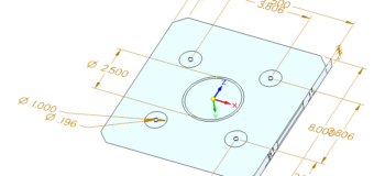
Notice that one diameter dimension in the lower left also was not selected. I’m not sure about why this happened. My IGES and DWG files are attached to this article as examples in case anyone else would like to explain what’s going on here.
Once you have one view selected, click Next and select the next view. I did not have to use the Fold Line options, I imagine these are for auxiliary views.
You need to also get the Primary View Orientation selection correct. For this you may have to refer to your existing part model, if you have one. The XZ plane is considered to be the Front. XY is the Top (or bottom, depending on how you want the views rotated). I think a wizard interface should explain more about details such as this.
Of course if the drawing views are not 1:1, then you need to specify the scale as well. It’s points like this where I get maybe a bit too picky. I think the word “Scale” here is ambiguous. If “Scale” is a noun, then what it really means to say is “specify scale of drawing views”, say something like 1:2. But if the word “Scale” is a verb, and it is really saying “how do you want to scale the views?”, then the ratio you enter would be backwards, so you would want to scale 1:2 views up by the ratio 2:1 to get to the model scale, which is always 1:1. Maybe I’m the only person who sees stuff like this, but it strikes me as potentially confusing.
When all views that contain dimensions are selected, and all the other options are set correctly, click on Finish. At this point, Solid Edge will either fold the views onto planes in a blank part, or place the views onto model faces in the existing part, depending on which option you selected.

It may be difficult to see above, but the two drawing views have been placed on the part. One step I didn’t show here, and the tutorials don’t mention is that maybe the view shows up on the wrong side of the part. That happened to me here, so I just selected the Part Copy1 body from the Pathfinder, and used the SteeringWheel to move the part down by the thickness of the plate. This makes everything line up the way it should. Your imported data doesn’t always come exactly the way the demo script is written, and sometimes you have to be able to improvise a little.
 Next, with the dimensions from the drawing views on the imported model, right click on one of the sketch features created by the Create3D feature in the Pathfinder, and select the Attach PMI option. This attaches the sketch dimensions directly to the 3D model, giving you editable PMI dimensions on your imported part.
Imported data is already pretty easy to deal with in SE wST, but when you can add drawing dimensions right to the model, that just makes it one step easier.
If you brought the views into an empty part, then you’ll just get a couple of sketches, as below.

From here you can use regions to extrude up to key points and rebuild your 3D model from the drawing view data. The PMI dimensions should automatically attach to the model faces when you do this.
PS: If you use my data, be aware that the pattern of holes is not square to the rest of the part.