Get the Most from Synchronous by using a little History
Before I was hired by Siemens, I was asked to present at SEU13. I still consider myself a new user, and not an expert in any way, so I had to say something based on past experience, but demonstrated in Solid Edge. One of the things that concerns me greatly is why so many users who have access to Synchronous Technology do not use it. I know there are types of design that do not lend themselves at this point to Synchronous, but those are stuff like complex shapes, where most Solid Edge users still don’t go. I think that maybe these people have tried Synchronous, and it failed somehow, and now those users have a bad taste in their mouths.
This presentation is really about what Ordered modeling is best for, what Synchronous modeling is best for, and why you need to combine them.
 Benefits of Ordered
Ordered modeling is great for a linear way of thinking. This, then that, then something else. It is great for making one thing dependent upon another. It allows you to segment the work, and compartmentalize tasks.
But there is no reason for solid models to be built that way. Assembly models aren’t built that way. Neither are drawings. Why are parts special?
When history-based modeling was created, the hardware couldn’t handle computing all of the geometry at the same time, so it was broken up to be solved one feature at a time. This method worked for the hardware, but it also made sense from a model building point of view. Pro/ENGINEER software made this very poplular.
Many people point to the design intent that you are able to create with history-based modeling as a benefit. You build the model in a certain way so that it will react to change predictably. When it comes down to it, most models are changed more often than they are created, so how it reacts to change is very important.
Of course there are still some features that have to be ordered in Solid Edge, such as any geometry based on splines or interpolated surfaces (Bluesurf, loft, bounded, etc.). This may change over time.
Downside of Ordered
History-based modeling also has an immense downside when the parent-child relationships started to crumble, and PTC knew this. The modeling methods that PTC taught students in the early 1990s minimized the downside, but the result was a very strict best-practice method for modeling. So-called “mid-range modelers” in the mid-1990s came along and removed the difficulty, but did not solve the underlying problems with parent-child relations. So we wound up with a modeling scheme were it was very easy to make models that were very unstable.
Benefits of Direct Edit
First of all, yes, I know that Synchronous Technology is the combination of direct edit, Live Rules, Procedural Features, PMI on the model, face relations, the Steering Wheel, and other great tools developed by Solid Edge . But I want to put all that other stuff aside for a moment. I just want to talk about the ability of Solid Edge to select a face and move, offset, or rotate it.
One of the benefits of this way of working has to do with design intent. With history-based modeling, once you build your design intent, changing the way the part reacts to change often involves completely recreating the part. But with direct edit, the design intent comes from the faces you select to move. Synchronous Technology adds Live Rules, which further allow you to control design intent through selections.
In history-modeling, the intelligence is in the model. With direct edit, the intelligence is in the selection. This allows you to change design intent in ways that would be nearly impossible with history-based modeling.
Downside of Direct Edit

It’s not all fairytale, though.If one of these methods was the hands-down winner, deciding between the two would be easy. But it’s not. Direct edit, even with all the added benefits of Synchronous Technology, suffers from difficulties when certain face types have to be extended, or when extending a face would require new topology.
 Crash Course on CAD Geek Terminology
In order to understand the downside of direct edit and to be able to overcome it, we have to understand some CAD geek concepts. These include NURBS, BREP and topology.
NURBS means “non-rational B spline”, but what it really means to you is that all faces in a CAD model want to have 4 sides, because the NURBS math makes U and V curves in perpendicular directions.
There are many situations when faces in a CAD model are not 4 sided, but there is always one of two reasons for a face not being 4 sided.
When the U and V directions intersect, as in 2 or 3 sided faces, that is because one or 2 of the 4 sides has become Zero length. This is called a degenerate point. Degenerate points cause problems with operations like rounds, thin walls, offsets, and other functions. Math and CAD don’t like to deal with Zero.
The second situation is when you have a trimmed face. NURBS allows for an underlying 4 sided or degenerate face, and a trimmed face. The underlying face gives your model a bit of “memory”, so it can remember its shape before a feature was added.
 In this image, the blue face is the underlying face, while the green section is the trimmed face. The trimmed face can be extended up to the extents of the blue face. This is the technology that underlies all CAD software, and drives the editability of models.
But there’s another layer of information here. Model faces are of different types. The type of face, the number of faces, and how those faces connect with one another combine to define the “topology” of a body. A cube is made of 6 planar faces connecting at right angles. A sphere is a single spherical face. A cone is a conical face and a planar face where the planar face is perpendicular to the axis of the cone.
The following image organizes the topology types from “most editable” to “least editable”.

Planar faces can extend infinitely in any direction. The U and V curves are straight lines. A cylinder can extend infinitely along the axis, but intersects itself in the other direction. Notice as you go from upper left to lower right the shape gets more complex. Lines can be extended infinitely. Circles and ellipses always intersect themselves, and splines cannot be extended.
The extendability of the faces on a part determines how well you will be able to use direct edit to change the model. Using less of a face is never a problem. Extending it can be.
 So when you have a part that looks like this, and you can’t move the hole in the center of the boss, now you know that it’s probably because of the complex faces created by the fillets around the tombstone shaped boss. That error message isn’t helping you understand what’s going on, but the concepts above will.
With this part, if you remove the fillets from around the boss, you can instantly move the hole and the entire boss without any difficulty  or cryptic messages.
Solid Edge allows you to remove fillets just by pressing the Delete key
The final CAD geek term you have to learn to understand why direct edit works or doesn’t work is BREP. BREP is short for Boundary Representation. This means the collection of faces that represents the outer skin of the part.

In the image above, you see that deleting rounds doesn’t work. When rounds are deleted, the neighboring faces are extened to intersect, but in this case, the original faces (shown in green) have been completely consumed by the rounds (removed from the BREP). To put them back in the model, you have to sketch the tombstone shape and extrude it over the other geometry. This is one serious flaw in the whole direct edit method – consumed topology cannot be easily replaced.
The answer to this is to only put rounds in as Ordered features. Since rounds should be added last anyway, this works out great. With rounds added last, the model has predominantly prismatic faces, which can easily be edited by direct edit, and can be edited very intelligently with Synchronous Technology.
To me, this removes all of the objections I have about working in either mode (Ordered or Direct) exclusively, covers over the weaknesses of both modes, and gives me more confidence in my CAD data.
 Mixed Methods
Synchronous is so powerful and flexible that you’re really missing out if you’re not using it. But you need your model to remember some BREP fundamentals, which is where history comes in.
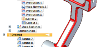
In the model shown to the right, all the gray is Synchronous, all the red is Ordered. The underlying prismatic model is very editable.
Beyond rounds, you might also add to the list of ordered features with chamfers, draft, and cosmetic features such as extruded text. The main point of removing items from the Synchronous body is to leave it as editable as possible. In this scenario Ordered features could be looked at as finishing features, cosmetic, not necessarily essential to the function of the part.
Summary
If you have ever struggled with getting Synchronous edits to work, you owe it to yourself to try this method. Simplifying the base feature to a prismatic shape with hard edges greatly increases the editability. You don’t lose anything by putting the other features in Ordered. Give it a try and come back and share your results.


Comments