E3.series combined with Solid Edge ensures seamless wire harness design

Zuken and Siemens connect electrical design and mechanical CAD systems, helping engineers ensure electrical harness design accuracy. This technical solution brief from Design World explores how electrical wire harnesses designed using Zuken’s E3.series can be imported into Solid Edge for routing around a mechanical assembly.
With a simple click, electrical and mechanical engineers using Zuken’s E3.series and the Solid Edge Wire Harness design module can trade electrical wiring designs and work collaboratively on the many components that combine electrical and mechanical aspects of machinery and equipment. The linking of electrical wiring designs from Zuken’s E3.series and the Siemens Solid Edge CAD program assure mechanical engineers that electrical wiring harnesses are accurately integrated into their design before it heads to manufacturing. Electrical and mechanical engineers can work closely together to create subsystems or products that include both electrical and mechanical elements.
 Craig Ruchti from Siemens Solid Edge discusses electro-mechanical design best practices
The partnership begins when the electrical engineer designs the electrical schematic within E3.series. That schematic and the associated information is sent to Solid Edge, says Craig Ruchti, a Solid Edge application engineer. The electrical data is transferred using the E3.3D Routing Bridge, which connects the Zuken and Solid Edge software and is accessed with a button click in Solid Edge. Transferred to Solid Edge are electrical harness details such as wires, connectors, terminals, splices and net-lists. Mechanical engineers, with the help of the Solid Edge Wire Harness module then position the wires, cables and connectors in the 3D mechanical assembly. “The linkage really enhances simplicity and ease with which these things are done,” Ruchti says. “It’s really intuitive, whether you’re running wires around a 3D mechanical assembly or creating cables or bundles.”
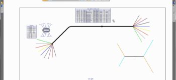
 Zuken’s E3.3D Routing Bridge is used to transfer comprehensive wiring data to and from Solid Edge
Ruchti adds “You need consistency on both the electrical schematic and 3D side and this collaboration gives you that consistency. The E3.series library also understands the color, size, weight of wires and bend radii needed and delivers that information directly into Solid Edge.”
 Wires can be added to cables, and cables can be split in the Solid Edge Wire Harness module
Once in Solid Edge, initial wire paths are automatically created and are connected to their specified connectors. This gives mechanical engineers their first chance to see how the wire paths look within the 3D model. But designers can also control the exact wire paths. “Solid Edge reads and makes appropriate connections throughout the model,” Ruchti says. “You can select an area within the 3D model that you want to attach terminals to and the system gives you the components and connectors to be placed.”
Because the Zuken application takes care of wire sizing and component information, mechanical engineers can change their designs without worrying about changing associated wire harness information. That information is updated automatically within the design and the information reflected on the E3.series side.
“If mechanical engineers didn’t have all the wires in the electrical schematic the first time around, they can still create them on the fly inside Solid Edge using the gauge, color, and physical properties associated with the wires within that system,” Ruchti says. “Then, they can be pushed back out and the electrical schematic maintained in E3.series is updated. Solid Edge also gives you feedback if, for instance, you have an improper bend radius,” he adds. “You’ll get automatic feedback and design checks.”
Should harness or mechanical information change during the design process, information can be returned to the electrical engineer for review, then back to the mechanical engineer for verification. This easy integration flow allows for fast collaboration, as both electrical and mechanical engineers can be working on the design at the same time, passing information back and forth as they complete the detailed design.
 Solid Edge supports the creation of the nailboard diagrams that are required to manufacture wire harnesses
When the design process is finished, the required manufacturing information is created. E3.series automatically generates the final wire harness BOM and the information for the nailboard diagrams required for wire harness manufacturing is also created.
Most products today integrate mechanical and electrical features. So, it’s essential that technology provides the ability for engineers from different disciplines to work concurrently. The integrated systems give engineers consistency on both the mechanical and the electrical side, significantly speeding design and product development, and thereby giving companies an edge over their competitors.
You can access a free test drive of Zuken’s E3.series and run through an online tutorial by yourself, and a 45 day free trial for Solid Edge is also available. The Solid Edge Wire Harness design module is included with Solid Edge Premium, or as an add-on for Solid Edge Classic and Foundation. You can also watch a video showing the integration between E3.series and Solid Edge.


Comments
Leave a Reply
You must be logged in to post a comment.
paito cambodia
Paito Hk
Paito Hk