Does it Really Matter “How” You Do It?
I’m going to keep on working through the piano bench I started last time. When I worked with history-only CAD, I spent a lot of time worrying about “how” to do things. It mattered because how you created something affected how you could edit it. The argument may have been academic to some extent, but I spent several pages of my books dedicated to the “how” and “why” questions. But now, working on this small assembly, I was faced with several ways to make some new features, and I didn’t want to make any stupid mistakes.
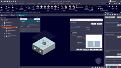
 Last time we looked at this assembly, I just had the four legs in place. The skirt part was already built, so now let’s put it on. The way I did this was I just made it to a random size, mated it into place, took a measurement, and then resized it to fit. Maybe I could/should have done this directly in the assembly to save some jumping around.
I didn’t make all the individual pieces that you would need to build from molding or board stock. That can be handled easily enough with some of the multi-body tools. I guess that sort of detail depends on how the part is going to be made, or what your purpose is for the data you are creating. In any case, I’ll go through how to break the skirt part up into bodies. I’m interested in how you real furniture designers actually handle this sort of thing.
The next piece to add to the assembly is the stringer to add some stability to the legs. I made one, saved it, then saved a copy, made the copy shorter, and put them both into the assembly.  Solid Edge has several very cool tools under the Replace Part tool (Home > Modify > Replace Part). If you have an existing part in an assembly and you want to change an instance to a different part, that’s easy. The Replace Part tools in Solid Edge really go a long way to make the assembly environment less scary than it is in other software. I love these tools. You’ve always got options.
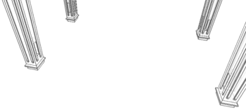
Anyway, so I placed one stringer, made a second instance of it in the assembly, and changed the second occurrence to a new copy using Replace Part with Copy. Works great. The  stringers are shown in the image to the right in the transparent green. Notice that they interfere with the legs. This was the big problem. How should I handle that I needed to accommodate slots in the legs, and the legs are all the same part just patterned around?
I don’t know what I “should” have done, but here’s what I did. I edited the leg part in the context of the assembly, and used the assembly based Boolean functions to subtract the stringers from the initial occurrence of the leg. In ‘Works, this would have caused quite a kerfuffle, not to mention if I had chosen an occurrence of the leg other than the initial occurrence, I might have had a looping reference.
So adding this feature to the initial occurrence of the leg gave me slots in all the occurrences, but they were all in the wrong locations. This was actually surprisingly easy to deal with.

I’m not sure if you can see it here, but the Mirror feature in the assembly allows you to control the relative position of the mirrored occurrence using the Action column in the Mirror Settings Step. While this works great, I wouldn’t mind an interface that was maybe a little more expansive. It wouldn’t be a bad thing to be able to see all the elements in the three steps at the same time, Select Components, Select Mirror Plane, and Mirror Settings. I don’t see any reason to force collapse all of this, and then push out this big bulky dialog box.
Anyway, the three available “actions” were Mirror, Rotate, and Exclude. Between Mirror and Rotate I was able to get what I needed. You might be able to make out in the image below that the slots are all turned the correct directions.

That’s really all that went into putting this together. There were a couple of questions that kept haunting me, though. I kept wanting to mate the parts up to planes. Part planes mated to assembly planes. Is this not possible in Solid Edge? I can’t see the part planes or other features in the assembly Pathfinder.
Oh, and one other thing. Because I just moved the first leg into place using the Steering Wheel, I didn’t have any sort of mates locking it into place. For me, this really isn’t a problem except for one thing. I use a Spaceball. The Spaceball driver doesn’t have an undo. So if you accidentally grab a part with the cursor, and move it with the Spaceball, consider that part moved. In order to get it back where it was, you have to hope you saved the assembly at a reasonable point. This is not Solid Edge’s fault, it’s 3DConnexion’s. They had the same problem in my previous software. One way to avoid it is to disable moving parts in the assembly.
So, now I have to ask, does it really matter how the slots in the leg were made? A true fan of associativity might say “Yes, now if you change your stringers, the slots won’t change”. Yes, that’s true. Unless I have the assembly open, make the change in the assembly, and select the face of the stringer and the face of the slot in order to make the move. This is in-context design intent only when you need it.
Now looking back at this, I think I would prefer to mate the first leg into place rather than just moving it. That at least would give me something concrete to start from. I would probably also draw the skirt sweep path sketch right in the assembly, so I have the advantage of inter-part methods without the overhead.