Dealing with Mesh Bodies in Solid Edge
Dealing with Mesh Bodies in Solid Edge
Steven Sheldon 2019
With the proliferation of 3D scanned data, it is becoming more common to have to deal with importing such data into Solid Edge. To people familiar with traditional CAD data, it may be puzzling as to how “mesh” bodies behave when brought into Solid Edge. Traditional CAD bodies, whether created in Synchronous or Ordered mode, have distinct faces, separated by clearly defined edges.


Traditional CAD body. Note distinct faces and edges.
We can convince ourselves that the model has faces simply by hovering the cursor over a face in Synchronous mode, or trying to place a sketch on a planar face in Ordered mode.

Face highlights on traditional solid body.
Mesh bodies can be generated either by CAD software (Solid Edge Convert to Mesh command, or by exporting a .STL model), or by 3D scanning software. CAD-generated mesh bodies tend to be “perfect”, in that for objects like cuboids the edges and faces appear just as they were when they were created as traditional bodies. And geometries that were originally planar, perpendicular, or parallel will generally still be so.
Bodies converted to Mesh inside Solid Edge
When we convert a traditional body to mesh within Solid Edge using the Convert to Mesh command, because Solid Edge created the original geometry it knows that certain faces were “analytic” faces before the conversion process. That is, Solid Edge knows which faces are planar, cylindrical, toroidal, or conical. When we convert this body to mesh, Solid Edge marks the facets that make up the new mesh body regions with the correct analytic tags so that even though the body is a mesh, certain collections of facets will behave like their traditional analytic counterpart faces.

Converting a traditional body to mesh inside Solid Edge.
So, here we can see a cube that has been converted to Mesh within Solid Edge. As you can see, if we hover our cursor over a “face” (really a collection of facets that now make up the face), Solid Edge recognizes that this was once a planar face and so will treat it as one for certain purposes even as a mesh body:

Solid Edge still recognizes this as a “face”, even though it is a collection of facets.
You can use these “marked” facet collections like faces for the purposes of sketching, creating assembly relationships, placing holes, and other things. You can even perform Synchronous edits on them (i.e. move). You should use caution when making extensive edits to mesh bodies as it has a tendancy to cause the mesh density to increase which can impact performance. SE2020 has a new Remesh command to help users deal with this.
Imported CAD-generated mesh bodies
However, if we import a mesh body, perhaps one that was exported from a traditional body as a .stl file, and then opened in Solid Edge, no analytic tagging of facets has happened. So, Solid Edge cannot tell which collections of facets make up a face. Instead, the model has only one face. In a shaded view with visible edges, we can see that there are no visible edges shown.

No visible edges on shaded view with visible edges
And in wireframe mode if we hover the cursor over a “face” we see that the entire model lights up!

Entire model highlights as there is only one face on an imported mesh body.
Imported 3D Scanned mesh bodies
3D scanned mesh bodies that are imported into Solid Edge have the same problem as CAD-generated imported bodies, in that they come in with only one single “face”, no matter what the model might look like on-screen. But in addition, 3D scanned data suffers from other problems. No matter how perfect the scanned object was, and no matter how perfect the 3D scanner is, the facets will never be as perfect as a CAD-generated body. This means there will not be perfect sharp corners between the faces of a cube. Moreover, however close they were, faces that should be parallel or perpendicular to each other never will be. This is because of inaccuracies in the scanning process.
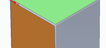
While this body was CAD-generated, I have deliberately skewed the faces and rounded all corners to simulate what you will see with 3D Scanned mesh bodies. I then exported it as a .STL document and re-imported into Solid Edge, again to simulate what you will see with imported 3D Scanned mesh bodies.


3D Scanned mesh bodies have no sharp edges, and faces are not parallel or perpendicular to each other.
Working with imported mesh bodies
As we have seen before, imported .stl bodies only have one single face. So if we hover our cursor over this 3D scanned body the entire body will highlight:

Imported mesh body has only one face.
In addition to this, 3D scanned bodies often import the body into a random position in space:

Body in random location in space.
Such bodies may seem difficult to work with. There are no base coordinate systems or reference planes aligned with the model that you can use for defining views that are orthogonal to the model, nor for placing any new geometric features (cuts, protrusions, holes). And, the model itself has no faces that can be used for reference.
What then, are we to do?
The answer lies with the Solid Edge Reverse Engineering tools. In particular, we will use the Identify Regions command to apply analytic tags (plane, cylinder, etc.) to collections of facets that we choose.
With actual 3D scanned mesh bodies, the facet count is generally very high (thousands). The Solid Edge Automatic Regioning command works well with these kinds of mesh bodies. It does not work well with CAD-generated mesh bodies, because planar faces are expressed in the simplest accurate method possible – two triangles. This does not give enough facets for the Automatic Regioning command to work. Solid Edge 2020 has a Remesh command that will allow you to increase the mesh density on bodies to enable Automatic Regioning. But in 2019, we will simply use Manual Regioning. Of course, even in SE2020 you can always use Manual regioning.
How many faces you choose to extract from your mesh body depends on your purpose. If you wish to remodel the body as a traditional body, then you may wish to extract many facet sets as faces. If you only wish to reorient the body in space with respect to a coordinate system, then you will need less.
When we launch the Manual Regioning command, by default we are in “paint” mode. This allows you to use the mouse cursor to “paint” facets to designate them. While we can paint them any color and use them, certain colors will automatically be interpreted by Solid Edge as analytics.

Analytic face colors for Solid Edge.
For some purposes, merely identifying regions of facets by their proper analytic color will be sufficient. For example, if we designate a planar set of facets as yellow, then in Solid Edge we can use the Look At Face command to look at that face straight-on. Or, we can sketch on it to create new features. Or, we can place holes on it.


Designating a planar region and using a designated planar face to view a body straight-on to that face.

Using a designated planar face to place sketches and holes.
For other purposes, we may wish to manually extract the regions as particular kinds of surfaces. In this case, we may paint the facet collections any color we wish, as when we extract the regions as surfaces we will specify the kind of surface we want at that time.

Manually identifying regions by random colors.
Next, we will extract surfaces from the regions we have identified, using the Extract Surfaces → Fit command. On the command’s QuickBar, we designate the kind of surface we are trying to extract. In this case, a plane. Then, we specify a tolerance. Beware of trying to specify too tight a tolerance – If you do, Solid Edge may not be able to find a plane that fits.

The Fit command QuickBar.

Extracting planar surfaces from the identified regions.
However, as we noted previously, with imported 3D scanned data these 3 planar faces will never be perpendicular to each other as they almost certainly were designed to be. This will make it impossible for us to align all 3 surfaces with the base coordinate system, which, of course, is perfectly perpendicular. It also makes it impossible to fully constrain the object as a component in an assembly.
To correct these issues, we will make use of the powerful Synchronous Technology in Solid Edge, and use the Face Relate commands to “true up” these extracted surfaces and make them perpendicular to each other.

The Perpendicular Face Relate command.
Use the Perpendicular Face Relate command to make all of the extracted surfaces perpendicular to one another. You will notice as they move into position that the Preview view very slightly deviates from the facets from which they were extracted. This is to be expected, and if the model was good, and the 3D scan was good, then the deviation should be small.

Trued-up extracted planar surfaces made perpendicular to each other.
Now we have 3 “datum” planes that correspond very closely to faces on our mesh model that we can use to move the model to the base coordinate system. If we trim these surfaces with each other, we now also have a vertex to define an origin and edges to define axes.

Trimming the extracted planar surfaces to define an origin and axes.
Next we can use the steering wheel to reposition the model to the base coordinate system origin.

Moving the model to the system origin.
In SE2019 it is tricky from this point to get the model back orthogonal to the base reference planes. I originally tried to create a rigid face relationship between the mesh body faces and the three extracted planes. Then, I thought I would use the Coplanar face relationship to move the entire set of faces, bringing the extracted planes to be coplanar with the base coordinate systems, with the mesh body coming along for the ride. Unfortunately, in SE2019 we did not allow the inclusion of mesh body faces in a Rigid select set. This has been enhanced in SE2020 and this workflow works very well then.
Probably the easiest thing to do (prior to SE2020) is bring the body into an assembly as a component, and use the extracted planar surfaces to mate the component to the base reference planes in the assembly.


Mesh body and extracted planes brought into an assembly and mated to the base coordinate planes.
Another option is to place an Ordered coordinate system on the model, at the intersection of the three extracted planes and along their edges. You can then use the Look at Face command to look at these reference planes and create Model views based off of them. These can then be used to place drawing views.


Using a coordinate system to define views.
If you want to bring the model to be aligned with the base reference planes, you can do so with careful use of the Steering Wheel. Use the 3D Sketch functionality to draw a line from the base origin along each of the base reference axes. Select the mesh body and the three extracted planar surfaces. Then position the Steering Wheel at the origin. Click on the blue dots at the end of the vectors, and drag the vectors until they are aligned with the edges of the extracted planar surfaces. Now you can rotate the model about one edge until the corresponding perpendicular edge is lined up with one of the end points of the lines we drew along the base coordinate axes. Repeat this for each axis of rotation and you will end up with the model aligned with the base coordinate system.


Using the Steering Wheel to bring the model to the base coordinate system.
SE2020 also has a new Align command that helps you re-orient mesh bodies to a coordinate system.
Hopefully this primer will provide some insight into the nature of mesh bodies and how to extract useful information from them.
* Opinions expressed are my own. No guarantee is offered to the accuracy of the provided information.


Comments