Custom Linetypes and Hatch Patterns Part 2
The previous article discussed creating custom line types using a simple combination of dash, dots and gaps represented by numbers.
This post takes it ahead by arranging multiple line types horizontally, vertically or inclined to create a Hatch Pattern which can be used in the Fill  command.
The process begins with creating a Hatch Style from the Style dialog invoked from the Styles button  on the ribbon’s Home tab – Dimension group.
To create a hatch pattern of squares as shown in figure below, imagine a line type called ForSquares once used at an angle of zero and again at 90 degrees, superimposed to create the squares:

Define the ForSquares line type with parameters as below using technique desribed in the previous article.

Next click the Style button on the ribbon bar, Home tab, Dimension group and in the Style dialog, select Hatch from the Style type list. Click the New.. button. Type the name Squares in the Name text box.

Take the Pattern tab and from the Type drop down list, select the ForSquares line type.
Specify the other element properties as shown in image besides.
The spacing and Y-offset values should match the Length and Gap values in the line type definition so that the squares are both formed and align uniformly.
Note that the angle value is 0 meaning the horizontal line is being defined.
With this, also note the linetype preview in red in the image in the top-right corner of the dialog.
Click the Copy Element  button.
The line definition gets copied and the element count increases to 2 as seen in the spinner 
For the second line element, change the last value for Angle to 90. These two lines with the dashed pattern called ForSquares are superimposed to form a hatch pattern.
Click OK and Apply to close the Style dialog. Invoke the command again and from the Style type list, pick Fill to create a Fill style that will use the Squares hatch pattern. The Fill style can be named Squares as well.
The new Fill pattern then becomes available under the ‘Fill – Style’ list on the Command bar for the Fill command.
Using this knowledge, more complex looking hatch patterns can also be broken into lines and identifying and defining their line types. For example the Honeycomb hatch pattern has stacked hexagons which might appear quite intimidating at first, but there are simply three lines at 0, 60 and 120 degrees all with the dashed line types with varying values of Gaps and dashes.

Solid Edge itself can be used for this purpose. Simply draw a hexagon using the Polygon  command and then stack few more by copying.
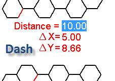
The first dashed line is identified as highlighted in red in images besides and the Dash and Gap values can be measured, also as shown.
Hence the first element for the pattern will be defined for this with angle zero, the second element at angle 60 and the third at angle 120 degrees.
In the Solid Edge help for this topic, under section 3 [c] (B) iii, not much useful information is available except for Use the Type, Width, Spacing, and other options to adjust the appearance of the current element pattern.
 As a result I have not been able to explore beyond a certain limit as to how the measured distances on the identified lines can be mapped to the dialog fields to generate the desired pattern.
For the second line, the various measurements would be as shown besides.
And the third line would be the one inclined at 120 degrees with similar measurements.
The Radial element type with an additional option to specify a promary:secondary ratio sure has potential to churn out stunning patterns especially when combined with linear elements, but this will remain untapped for a long time to come.
~ Tushar Suradkar


Comments