Colors in Solid Edge
A couple of weeks ago I asked for some suggestions for blog article topics on the forum. One of the topics suggested was “adding/creating visual styles/textures”. That’s a bit of a softball topic after the Virtual Components posts. Still, it’s important, and maybe a topic that new users will benefit from.
 As is becoming usual for me when I learn new Solid Edge functionality, something that originally looked simple becomes much more involved once I start diving into the details. At first, I only saw the Part Painter, View Overrides and the Color Manager when looking for color controls. Solid Edge gives an amazing level of control when it comes to creating new styles of visual options.
Setting the Style
The Style (View > Style > Styles) dialog is the beginning of a wild journey of visual and display customization options. In the top selection box, the two items we are most concerned with at this time are the 3D View Styles and the Faces Styles. We have talked about the Dimension styles options in a previous article on units and standards.
Color is not the only visual property that you can control for Solid Edge parts. Face Styles in Solid Edge consist of the following factors
:
- Name (and possibly base style)
- Edges (colors/line pattern/width)
- Face color (diffuse/specular/ambient/emission)
- Texture (image)
- Bump map (image)
- Appearance (optical properties such as shininess, reflectivity, opacity, refraction, cast and accept shadows)
- Reflection Box (background that will be reflected on parts from all six sides, or from a hemispherical image, depending on the Define Using setting)

From all of these available settings, you can either modify existing styles or create your own from scratch. This functionality is much more powerful than I initially thought.
 To the right is a part with a special style that I made just to show what can be done. Yes, I realize it’s ridiculous, but there will come a day when someone needs to makes something like this, and now they can do it. First, I assigned a Diffuse color of purple, then a red specular color, and a light blue ambient, with an Emission of dark blue. Emission is the color the object would emit if it were a light bulb (great way to make glowing lights on models). Under Appearance, I made it very shiny, and in Reflection Box, I assigned a picture of the sky. Then I set up the lights in the View Overrides dialog, which we will come to shortly. There are also some shadow settings which enable a part to cast shadows on itself if the lights are in the right position. This part above is shown upside down, so there is a shadow on the inside.
If you haven’t caught on by now, what I’m saying is that Solid Edge parts don’t have to look so dull and drab. And you don’t need a rendering package or an art degree to make parts/assemblies/scenes that look a little more interesting. The main thing you need here is an interesting image in the Reflection Box panel, and parts that are at least a little bit reflective. Shadows also help a scene look more realistic.

Ok, so that’s how to create a style that is interesting.
Painting Parts
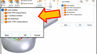
To apply a style to a part, use the Part Painter tool. The Part Painter is easy to use once you get the workflow down. If you just start flailing away at it, you’ll get frustrated, so stop pounding the keyboard and read this for a second.
 To use the Part Painter, first, initiate the tool by clicking on the icon, shown to the right.
Once you do that, you’ll get the Command Bar shown here to the left. I’m using the vertical Command Bar. If you use the horizontal setting, you will see something else.
You won’t hear me say this often, but ignore the Prompt Bar. It tells you to “Click on elements to apply paint to”. Besides being grammatically tenuous, it is also leaving out some details.
First, you need to set the style that you want to apply. Then set the selection type you want to apply the style to. If you want to color a selection of faces that aren’t a feature, just click Face, then make your selection. The style is applied as soon as you make the selection.
Overrides
When you’re dealing with colors/styles, on multiple levels of the model, such as faces, features, bodies, components, instances, etc, you need to remember that there is a hierarchy for overrides. And then there are some options to override the overrides. Hang on, this gets a little bumpy.
The part color is overridden by the
- Body
- Feature
- Face
- Assembly
- Assembly Feature
- And after that it gets a little fuzzy
So if you remove a Face color and there is no Feature or Body color, the face will return to the default Part color. To remove a color, use the Part painter, with the Style set to None, and then select the faces you want to set back to the default style.
This override business takes a little getting used to, but it will help you make sense of a part or assembly with multiple layers of Styles applied to it. When you have an assembly of parts, it is best to change the color (ahem, style) of individual parts in the part window rather than in the assembly window. Doing this will help you from becoming more confused than necessary regarding the overrides.
Color Manager
The first place you need to check before starting to change the colors of parts is the Color Manager (View > Style > Color Manager). This enables you to use global settings for all parts, or each part file can control its own color. When global settings are used (called Use Solid Edge Options color settings in the Color Manager dialog), Active, Inactive, and Construction (surface parts) are controlled as groups.

The Solid Edge Options color settings can be found at the Application Menu > Solid Edge Options Colors, and allows you the settings shown below. Using the Color Scheme selection at the top, you can establish various settings for different color schemes. For example, you might have different color schemes for working with surfaces, large assemblies, electrical assemblies, or if you’re a contractor, different customers might require different color settings.
The advantage to this way of working is that all the parts are the same color, but features with different functions will be colored differently and be easier to identify quickly. In most situations, I see the “Individual Part Styles” option as being the best.
The dropdown color selection lists (for the Construction in the image below for example) offer you a list of color names spelled out with options such as clear, dull and glass. This makes it easy to get the same color every time, as opposed to a visual selector where matching colors can be difficult.

The options at the bottom of the Color Manager are:
- Show and allow assembly style overrides: This means that you can make changes to colors at the assembly level
- Show part face colors: This allows you to see part level overrides
View Overrides
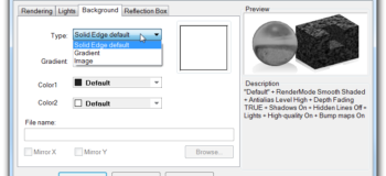
The final area to talk about with Solid Edge styles/colors is the View Overrides dialog. This was one of the first functions I leaned in Solid Edge because the gradient background can be turned off in the Background tab of this dialog. Let’s go through the options available here.
The Perspective option enables you to select none, 85, 50, and 30mm. The smaller the number, the more severe the perspective. Remember that most non-CAD users are used to seeing images without perspective. As CAD users we get used to all the edge being parallel, but others might be put off by that effect. So when you are putting together marketing images, or especially when you talk to an industrial designer, make sure to include perspective.
Antialias is what the computer does to smooth out jagged lines caused by angled or curved edges on a computer display. Solid Edge gives you None, Low, Medium and High setting options. High looks better, but it will tax your performance to some extent, especially when you have a large number of edges on the screen.
Render mode is just talking about regular shaded rendering, not photorealistic rendering. I like to work with “Smooth with VHL Overlay” turned on, but sometimes for presentation images, I turn off the VHL (visible hidden lines) option.

The toggles at the bottom of the Rendering tab are mainly self-explanatory. The toggles exist to simplify the display and save some compute power in large assemblies.
I have not yet discovered what Depth Fading does, although I would assume it would apply some equivalent of “depth of field” where items in the background are progressively out-of-focus.
Something to watch out for here is that the lights are tied to the Style. So parts may have different lighting arrangements that are based on the applied style. But also notice that the second tab on the View Overrides is a Lights tab. So you can override the lighting situation in the assembly. Lights can be of various colors, and come down from an adjustable angle.

The Background tab enables you to use a plain color (default white), a gradient color, or an image background. I prefer the white background for capturing blog images, but most people seem to use the default gray gradient. I set all my document templates to use the white background.
The final tab is the reflection box. This is where you can put an image to reflect on your parts. Having some sort of reflection helps make parts more realistic. You can look on the internet to find all sorts of industrial setting images, such as the inside of a factory. If your parts are reflecting a plain white background, they may as well not have any reflective property at all. Even an image of the sky can give images of parts a nice touch.
Summary
Solid Edge is far more advanced in the display options area than anyone has let on. I must say you guys are really good at keeping secrets. How things look is really a secondary function for a CAD product. The important thing is the ability to get the geometry and engineering right. But if you could use your CAD tool instead of a dedicated rendering software to create passable presentation images, wouldn’t that be a good thing?