Color in Drawings
 2D drawings have been dead for 30 years, if you believed CAD salesmen in the 1980s. Most of us knew that was wrong back then. Even today, there are only a few areas where drawings are truly extinct. 2D technical drawings continue to exist because they are easy to understand, and give us a standardized way of communicating. Even drawings printed on paper continue to exist. The fall-back for 2D extinction was that they would continue to exist but only electronically. Until someone prints one out.
So drawings haven’t become extinct. That’s because in most cases we need them, and really use them. Just because they haven’t become extinct doesn’t mean that they haven’t evolved a little to keep up with the times. Today I want to have a look at colors in drawings, much as we had a look at color in 3D models a couple of weeks ago. We saw that there are a lot of ways that you can use color in parts and assemblies to support documentation, purchasing, manufacturing, QA – just about every department under a manufacturer’s roof can have their own special color significance. In this post I’m going to talk about bringing that color to the drawing.
 Color on drawings has been something that’s been avoided for a lot of different reasons. Originally, color pencils didn’t erase as neatly as regular old black. And then copying large format color drawings would have been prohibitive too. Enter pen plotters, and you had to change a pen to get a new color. Or more advanced pen plotters, and switching pens took too long, or the colors always ran out and never got replaced. And still, with laser and ink jet printers, the ink costs extra, and is a hassle.
But drawings are all about communication, and color is a great way to communicate. Sure, it can get completely cocophonous with poorly selected colors (colors that don’t contrast with white or one another), but that’s why documentation standards are still developed.
Solid Edge has a couple of ways to set up drawings in color.
Shaded Views
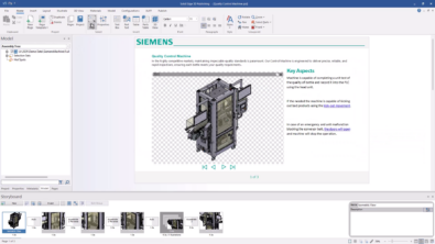
 You can create drawing views that look the same as your 3D model – using shaded views. In the view to the right, I used a grayscale view with edges. This is a nice option that I haven’t seen in other software I’ve used.
Shaded views are the easy ones. Colored wireframe views are more difficult unless you have your parts set up correctly from the start.
Colored Wireframe Views
If you are doing drawings of single parts, this turns out to be fairly easy. although it took me the better part of an afternoon to figure it out. If you are making an assembly drawing and want the parts on your drawing to be the same wireframe color that the parts are on the shaded model, you might have more work in front of you.
Make the following settings in the individual parts:

On the View tab, Style group, click Style, then Faces Styles, and select the style you’re using for this particular part. Hint: you might want to set up and save a template if you plan on using this in the future. Now click the Edges tab, and set the color that you want the edges in the drawing of this part to use. Just as a further note, you could create a new style for machined parts, sheet metal parts, purchased parts, parts sourced from ACME TOOL, or whatever. I get the idea that Styles is probably an underused area of the software because of the complexity involved in using it. Bob Mileti had something to say earlier about the complexity of some of the color options.
On one hand, there is a lot of detailed control here. On the other hand, it’s pretty complicated, and buried deep. There are other places to control the display of shaded edges, but this seems to be the one that will carry through to the drawing.

Ok, you’re not done yet. In the Color Manager (unlabeled in the Style group) make sure first that you are using the individual part styles option. Second, make sure that your Base Style for the part is set to whatever Style you just edited, which in my case was aluminum. In many cases, this style setting is “default”.
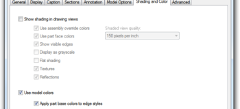
Still not done. Make sure that every thing is saved. Flip to the drawing (Ctrl-TAB for those of you who might not know that). Click on the view border or on view geometry, and select Properties from either the RMB menu or the Command Bar. Make sure the settings are set up like this (below).

When you have this set, the drawing view still may not be correct, so right click in the view and select Update. This is the step that hung me up. There should be a hotkey to that command.

The hose and the engine cover are the only two parts in the pressure washer model shown here that are set up correctly to use this method of working. I would need to go through the rest of the parts and get the settings correct.
The pressure washer 3d model, when set to display wireframe looks like below. It should be just a click of a button to make the assembly drawing view look just like the model. So either I’ve missed a big ‘ol easy button here, or there’s a big opportunity for someone to add one…

Colored wireframe drawing views have been avoided in the past, and sometimes those prejudices continue into the present without good cause. Section views rely on hatching to distinguish parts, but other types of views don’t have that advantage.
As far as I can tell, there is no simple way to just pick a part on the drawing view and change it’s line color (or line style/thickness for that matter). The general color interface in Solid Edge is extremely detailed, and very powerful, but it can also sometimes be a bit involved to find stuff.
Do you use color in your drawings? Are the colors random, or do you have some scheme for the colors?